
Ratio controller with dynamic ratio formation

a ratio controller and dynamic technology, applied in the field of ratio controllers, can solve the problems of limiting the use of the ratio controller, adding pressure or pressure lines, and burners to the ratio controller,

Inactive Publication Date: 2007-07-31
KARL DUNGS
View PDF10 Cites 34 Cited by
  • Summary
  • Abstract
  • Description
  • Claims
  • Application Information

AI Technical Summary

Benefits of technology

"The present invention provides a ratio controller without external pressure taps. The ratio controller has a main valve with an actuating diaphragm and a pulse channel to control the actuating diaphragm. This allows pressure tapping of the outflow chamber of the ratio controller selective or simultaneously at different measurement sites. The gas pressure occurring at the output of the ratio controller as a function of the gas velocity can be regulated to correspond to a stipulated gas-air ratio. The ratio controller can maintain this gas-air ratio over different load conditions. No external pressure taps are required for this. The formation of the correct pressure ratio at the gas nozzle is effected as a function of the pressure difference at the air feed. The pressure controller is set so that it roughly adjusts the static pressure at the gas nozzle. The output pressure set by the ratio controller can then be made constant over a wide power range. The adjustment can occur both manually and via a remote-controlled adjustment device. The control device can be connected to appropriate sensors that record the calorific value of the gas or the CO content, the O2 content, or the NOx content of the exhaust. Correction of the gas-air ratio can then be effected on the basis of these measured values. The technical effects of the invention include improved gas pressure regulation, simplified design, and reduced costs."

Problems solved by technology

Additional pressure taps or pressure lines, for example, from the burner to the ratio controller, represent undesirable limitations from the standpoint of the system supplier.
An additional pressure tap in the combustion chamber is often not present, so that use of this ratio controller is restricted.
In this arrangement, an undesired hampering of air flow develops through the throttle valve location behind the forced-air burner.

Method used


Image

  • Ratio controller with dynamic ratio formation
  • Ratio controller with dynamic ratio formation
  • Ratio controller with dynamic ratio formation

Examples


Embodiment Construction

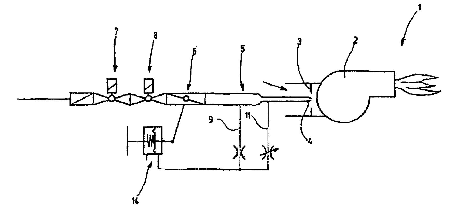
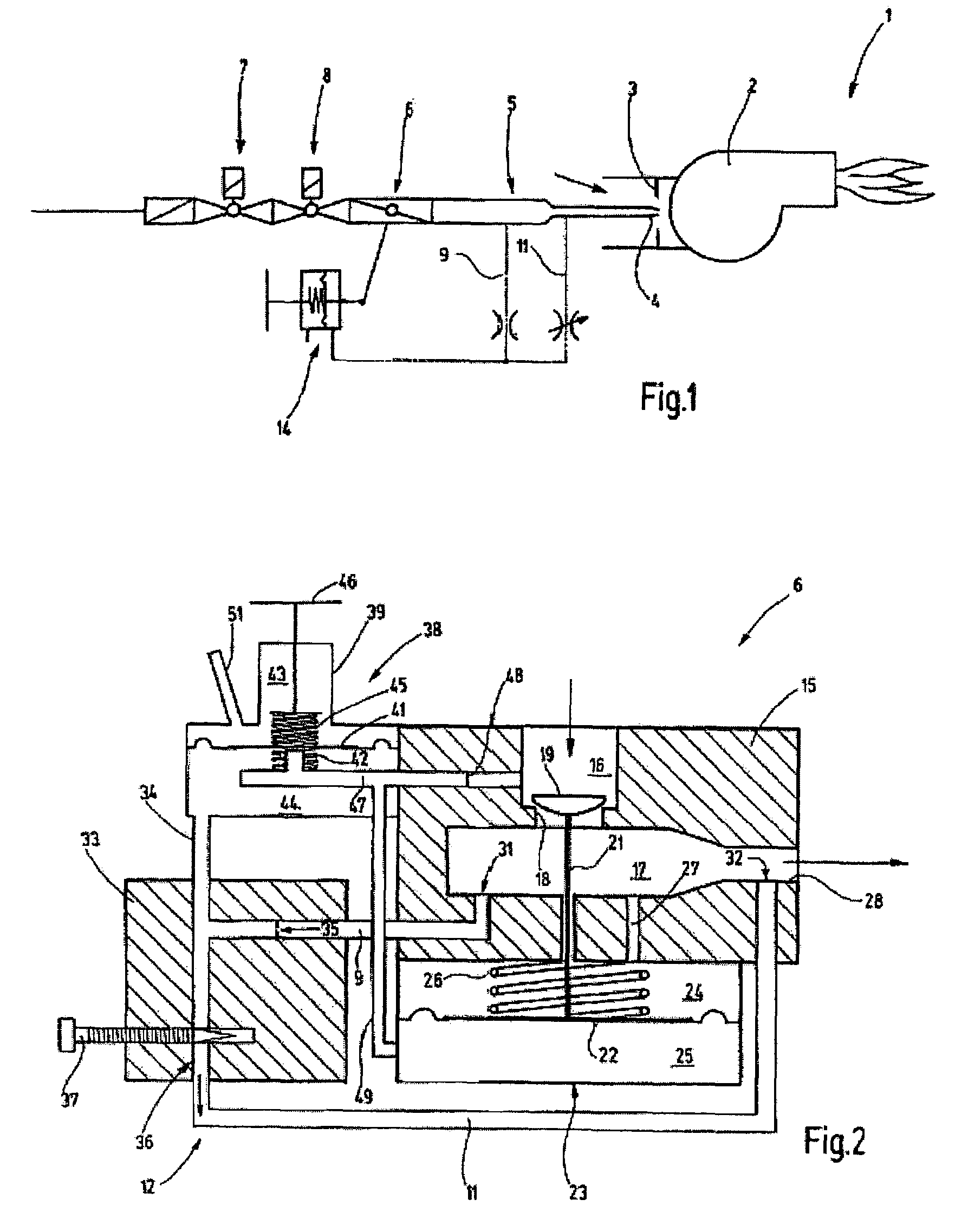
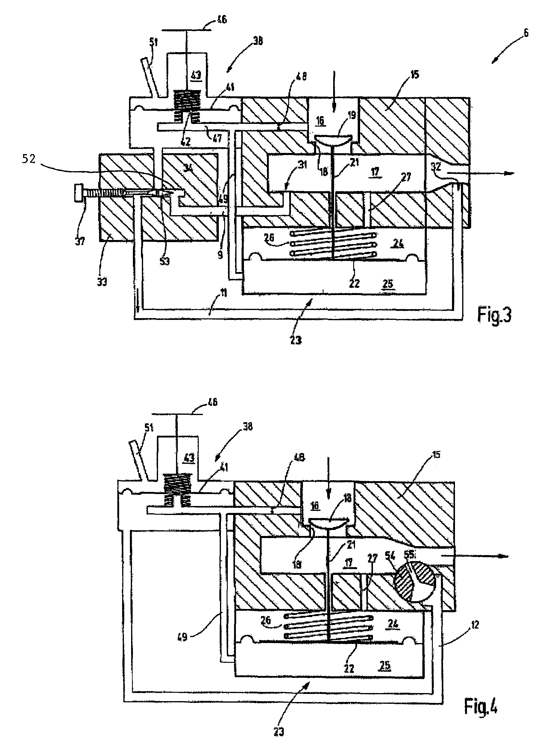
[0023]A forced-air burner 1 with a blower 2 connected upstream is shown in schematic form in FIG. 1, the blower drawing in a gas-air mixture. For this purpose, the blower 2 has an air jet 3 on the input side, in which a gas nozzle 4 is arranged. This is fed from a gas line 5, upstream of which a ratio controller 6 and control valves 7 and 8 are connected. The latter serve to release and block the gas. With control valves 7, 8 open, the ratio controller 6 serves to adjust a stipulated gas-air ratio independently of the supply power of the blower 2, i.e., its speed. The ratio controller 6 performs this merely by tapping its own valve housing or the gas line 5, without measurement or tapping of the amount of air. For this purpose, on the path between the ratio controller 6 and gas nozzle 4 at least two different flow cross sections are formed in the gas line 5 or in the housing of ratio controller 6, from which branches 9, 11 of a pulse line 12 branch off. This serves to control a cont...


PUM


Abstract

For adjustment of a desired burner gas-air ratio over the broadest possible load range without additional pressure tapping of the burner, combustion chamber, or air lines, a ratio controller is provided that permits adjustment of the gas flow as a function of counterpressure. For adjustment, the ratio controller has at least one position-variable measurement site, or at least two measurement sites, connected directly or indirectly via a pilot valve, to an actuating diaphragm via a valve block or throttle valve block. Depending on whether the control pressure is picked up more from one or more from the other measurement site, the gas flow and therefore the gas-air ratio can be adjusted to be larger or smaller.

Description

CROSS REFERENCE TO RELATED APPLICATIONS[0001]This application claims priority to German Application No. 103 40 045.1, filed Aug. 28, 2003, all of which are incorporated herein by reference.TECHNICAL FIELD OF THE INVENTION[0002]The present invention is directed generally to a ratio controller for fuel gas metering in gas burners.BACKGROUND OF THE INVENTION[0003]The invention concerns a ratio controller, especially for fuel gas metering in gas burners, for example, forced-air burners.[0004]In gas burners, a stipulated gas-air ratio must be set at the burners in order to ensure correct operation. The gas-air ratio must then be set independently of the load state. For burners that are in particular to be operated not only at nominal load, but also at partial load, this requires re-adjustment of the gas feed corresponding to air feed. The aim is to permit this with simple, robust and versatile devices.[0005]In the design of gas heating installations, gas boilers and gas burners, system s...

Claims


Application Information

Patent Timeline
Patent Type & Authority Patents(United States)
IPC IPC(8): G05D16/16F23D14/60F23N1/02
CPCF23D14/60F23N1/027F23N2035/20F23N2035/24Y10T137/7762Y10T137/7764F23N2235/20F23N2235/24
Inventor MOSES, JOHANN
Owner KARL DUNGS
Learn More