Leadscrew mechanical drive with differential leadscrew follower structure

Active Publication Date: 2007-07-31
RAYTHEON CANADA LTD
View PDF6 Cites 19 Cited by
  • Summary
  • Abstract
  • Description
  • Claims
  • Application Information

AI Technical Summary

Benefits of technology

[0006]The present invention provides a leadscrew mechanical drive with a selectable transmission ratio between the rotational rate of the leadscrew and the linear rate of motion of the leadscrew follower structure. The linear motion of the leadscrew follower structure may be selected to be faster or slower than that of the normal leadscrew mechanical drive, but the greatest advantage is achieved when the linear motion is slower than that of the normal leadscrew mechanical drive. In that instance, the speed reduction is accomplished entirely in the leadscrew / leadscrew follower mechanism. No modification to the motor or motor controller is required, and no separate speed-reducing gearbox is used. The leadscrew mechanical drive is inexpensive, light, and compact. High linear positional resolution and accuracy, coupled with a low movement rate, may be readily achieved. The leadscrew itself may be manufactured with a readily achieved thread pitch, so that no special manufacturing procedures are required for the leadscrew. Slippage between the threads, play in the structure, and backlash upon reversal of the direction of rotation of the leadscrew are minimized. The present leadscrew mechanical drive is suitable for all duty ranges, including light, medium, and heavy duty applications, but its greatest advantages are realized in medium and heavy duty applications where the rate of linear motion is relatively slow and the forces to be transmitted are relatively large.
[0012]In a conventional leadscrew mechanical drive where the thread pitch of the leadscrew and the thread pitch of the leadscrew follower structure are the same, the leadscrew follower structure closely engages the leadscrew over several turns and moves linearly by the amount of the thread pitch with each revolution of the leadscrew. In the present approach where the thread pitches of the leadscrew and the leadscrew follower structure are different and the threaded insert rotates on its bearing, the leadscrew follower structure moves linearly by the difference between the thread pitches with each revolution of the leadscrew, thereby achieving a differential drive effect. A small linear movement rate may be achieved by making the thread pitches of the leadscrew and the leadscrew follower structure close to the same but slightly different. Having a different thread pitch of the leadscrew and the leadscrew follower structure is not possible with conventional leadscrews, because the mismatch would lead to binding between the two threads. In this case, however, binding between the thread of the leadscrew and the thread of the leadscrew follower structure is avoided by angularly displacing the leadscrew axis and the insert axis by a small amount, and by providing for a loose fit between the two sets of threads.
[0013]Another important advantage of the present approach is that the efficiency of load transfer from the drive motor to the driven structure is about 90-98 percent, independent of the reduction ratio. The high efficiency is a result of the low friction between the leadscrew and the insert. By contrast, a conventional leadscrew mechanical drive has increasing friction, and thence decreasing efficiency, as the reduction ratio increases and the movement of the driven structure becomes slower. For a reduction ratio of 8000:1 and using a high-quality speed-reducing gearbox, a conventional leadscrew mechanical drive has an efficiency of about 50-60 percent, with a significant fraction of the drive power being lost to friction. The load which may be transmitted using the present approach actually increases with increasing reduction ratio, while the load which may be transmitted using the conventional approach decreases with increasing reduction ratio.

Problems solved by technology

The conventional leadscrew mechanical drive works well in many situations, but has limitations in others.
Some of these modifications have physical limitations that limit the ability to achieve the desired slow linear movement.
The ability to reduce the rotational output speed of the motor is limited by the structure of the motor windings, so that it may be necessary to use a special low-speed motor.
In any event, these modifications lead to an expensive, bulky, and / or heavy leadscrew mechanical drive that may not be suitable for the desired applications.

Method used


Image

  • Leadscrew mechanical drive with differential leadscrew follower structure
  • Leadscrew mechanical drive with differential leadscrew follower structure

Examples


Embodiment Construction

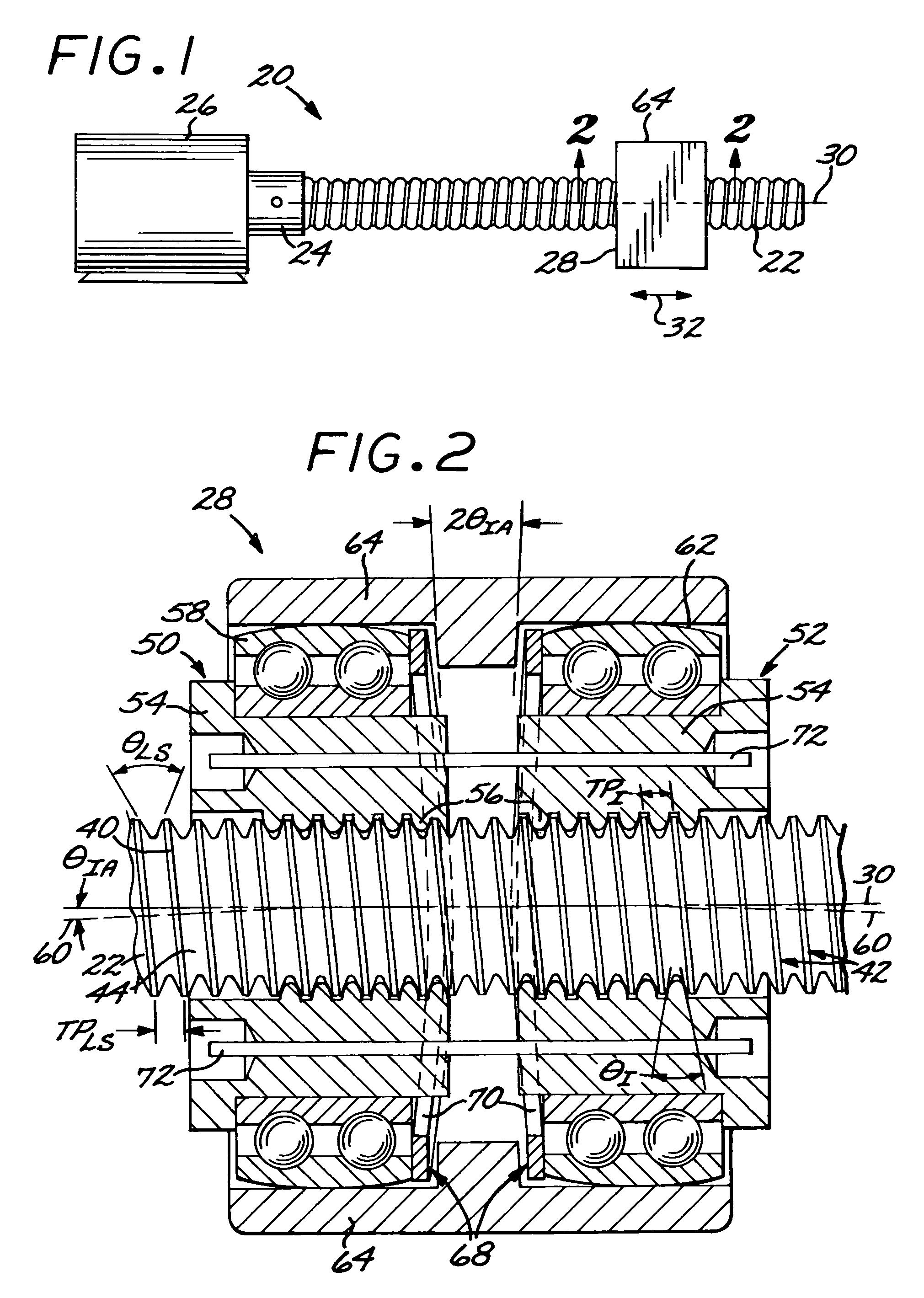
[0017]FIG. 1 depicts a leadscrew mechanical drive 20. The leadscrew mechanical drive 20 includes an externally threaded leadscrew 22 that is driven by a rotational output 24 of a motor 26 or other power source. The motor is preferably a synchronous motor such as a conventional high-speed motor, although other types of motors such as stepper motors may also be used. Preferably and as illustrated, there is no speed-reducing gearbox in the leadscrew mechanical drive between the rotational output 24 and the threaded leadscrew 22. A leadscrew follower structure 28 is threadably engaged to the leadscrew 22. As the motor 26 turns the threaded leadscrew 22 about its rotational leadscrew axis 30, the threaded engagement between the leadscrew follower structure 28 and the leadscrew 22 translates the rotational movement of the leadscrew 22 into linear movement of the leadscrew follower structure 28 in a linear movement direction 32 parallel to the rotational leadscrew axis 30. The leadscrew fo...


PUM


Abstract

A leadscrew mechanical drive includes a leadscrew having a leadscrew axis and a leadscrew thread with a nonzero leadscrew thread pitch, and a leadscrew follower structure engaged to the leadscrew. The leadscrew follower structure includes a threaded insert having an insert thread with a nonzero insert thread pitch different from the leadscrew thread pitch, which is threadably engaged to the leadscrew. The leadscrew follower structure further includes a bearing in which the threaded insert is received and which permits the threaded insert to rotate about the insert axis, a bearing support in which the bearing is received, and a preload structure which biases the insert thread against the leadscrew thread.

Description

[0001]This application is a continuation in part of application Ser. No. 10 / 271,479, filed Oct. 15, 2002, now U.S. Pat. No. 6,931,960 for which priority is claimed and whose disclosure is incorporated by reference.[0002]This invention relates to a leadscrew mechanical drive and, more particularly, to a leadscrew mechanical drive utilizing a leadscrew and a leadscrew follower structure.BACKGROUND OF THE INVENTION[0003]Most common electrical motors have a rotational output, but in many instances the structure to be driven requires a linear motion. There are a number of approaches to mechanically converting the rotational motor output to a linear motion. One such approach is a leadscrew mechanical drive in which the motor rotationally drives a threaded leadscrew. A leadscrew follower structure driven by the leadscrew engages the leadscrew and moves parallel to the axis of the leadscrew to convert the rotational motion to linear motion parallel to the axis of the leadscrew. The leadscre...

Claims


Application Information

Patent Timeline
IPC IPC(8): F16H27/02F16H25/22F16H25/24
CPCF16H25/2295Y10T74/19805Y10T74/19809
Inventor DEVENYI, GABOR
Owner RAYTHEON CANADA LTD
Why Eureka
Try Eureka