
Wireless mobile communication device having a speaker vibration alert and method of using same

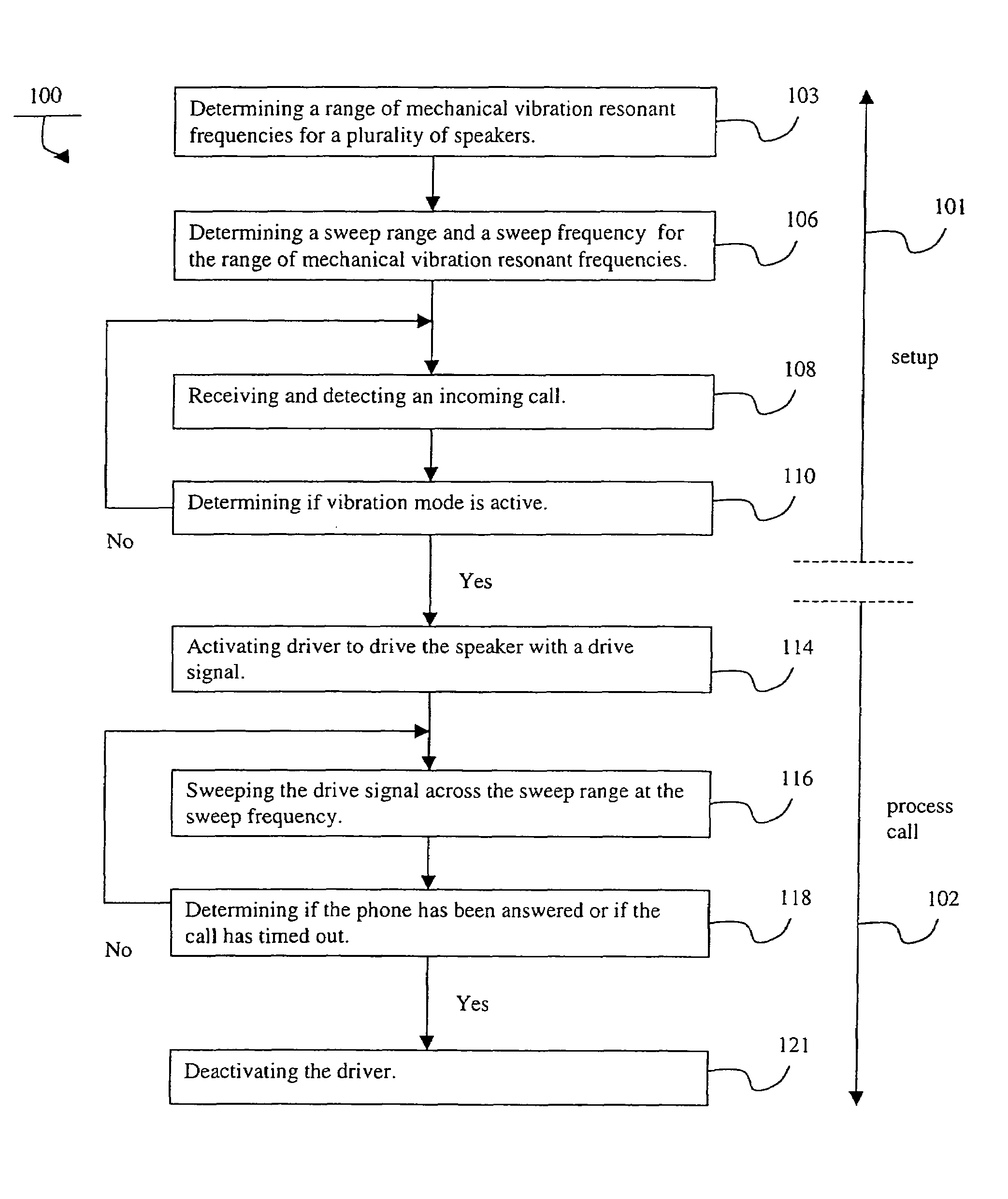
a wireless mobile communication device and vibration alert technology, which is applied in the direction of automatic frequency control, substation equipment, current supply arrangements, etc., can solve the problems of significant difficulty in selecting a speaker for the wireless mobile communication device, speaker vibration at that frequency is not sufficient, and it is difficult to manufacture wireless mobile communication devices with the same drive signal source. , to achieve the effect of increasing the driving signal, reducing the size, weight, manufacturing cost and power consumption of the mobile wireless communication devi

Inactive Publication Date: 2007-07-17
KYOCERA CORP
View PDF2 Cites 14 Cited by
  • Summary
  • Abstract
  • Description
  • Claims
  • Application Information

AI Technical Summary

Benefits of technology

The present invention provides a way to alert a user of a wireless mobile communication device through a speaker that resonates with the device's mechanical vibrations. This results in a more effective alert as the drive signal effectively drives the speaker at its resonant frequency. The invention also eliminates the need for a separate vibration device, reducing size, weight, part-count, manufacturing cost, and power-consumption.

Problems solved by technology

This variation in mechanical vibration resonant frequencies makes it difficult to manufacture wireless mobile communication devices with the same drive signal source.
If the drive signal source has only a single frequency, some of the speakers in the group will not vibrate sufficiently at that frequency.
This presents significant difficulty in selecting a speaker for the wireless mobile communication device and therefore in manufacturing the wireless mobile communication device with the speaker.
The beat frequencies are caused by the constructive and destructive interference of the composite signal's multiple constituent frequencies.

Method used


Image

  • Wireless mobile communication device having a speaker vibration alert and method of using same
  • Wireless mobile communication device having a speaker vibration alert and method of using same
  • Wireless mobile communication device having a speaker vibration alert and method of using same

Examples


Embodiment Construction

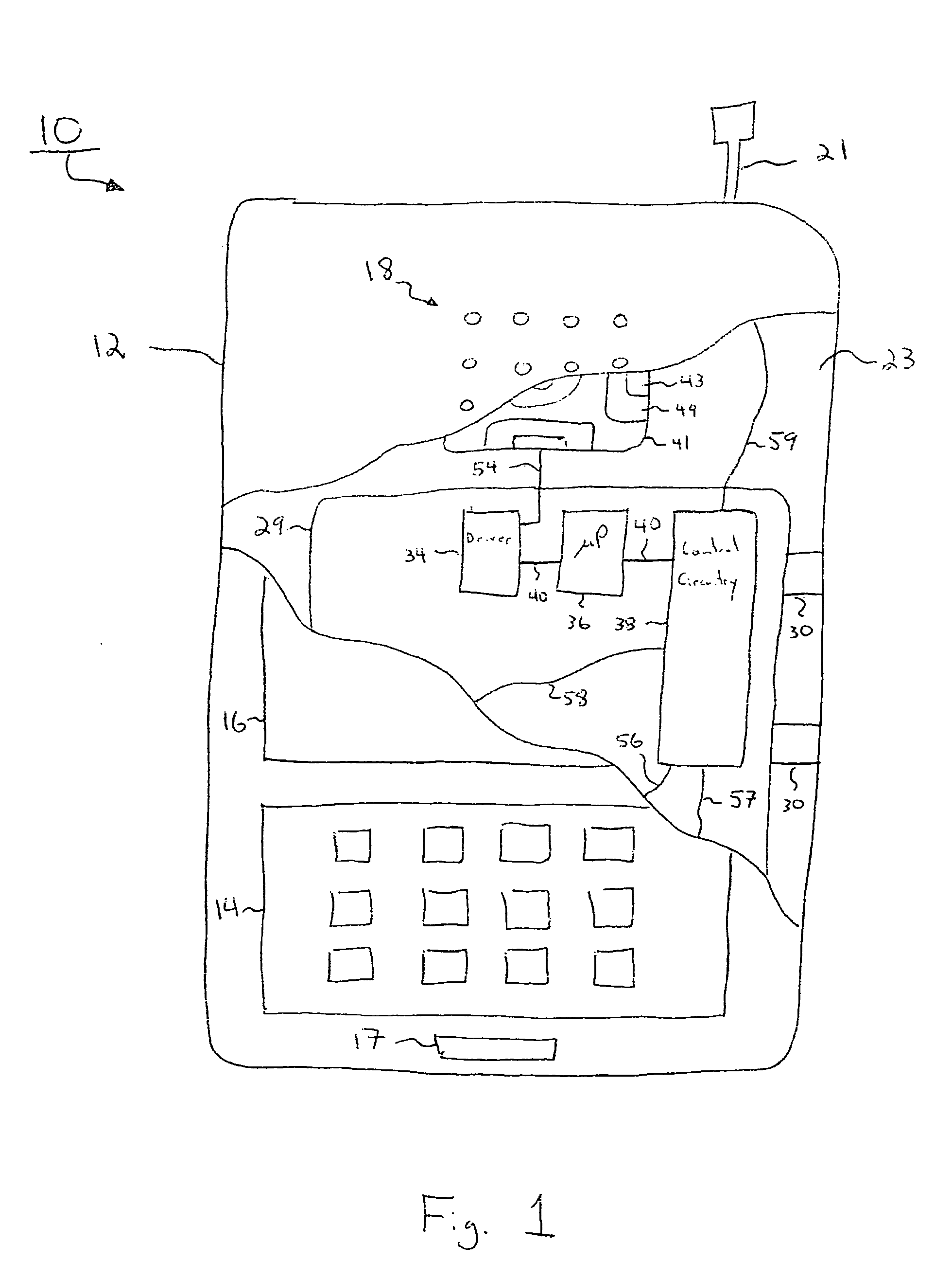
[0019]A wireless mobile communication device is shown in FIG. 1. More particularly, the wireless mobile communication device is shown in the form of a wireless handset 10. The wireless handset 10 has a housing 12. A keypad 14 and a display 16 are attached to the housing 12. The keypad 14 allows a user to input information and issue commands for the wireless handset 10. For example, the user may dial a phone number by using the keypad 14. The display 16 provides information to the user from the wireless handset 10. For example, the display 16 may show the phone number of an incoming call.

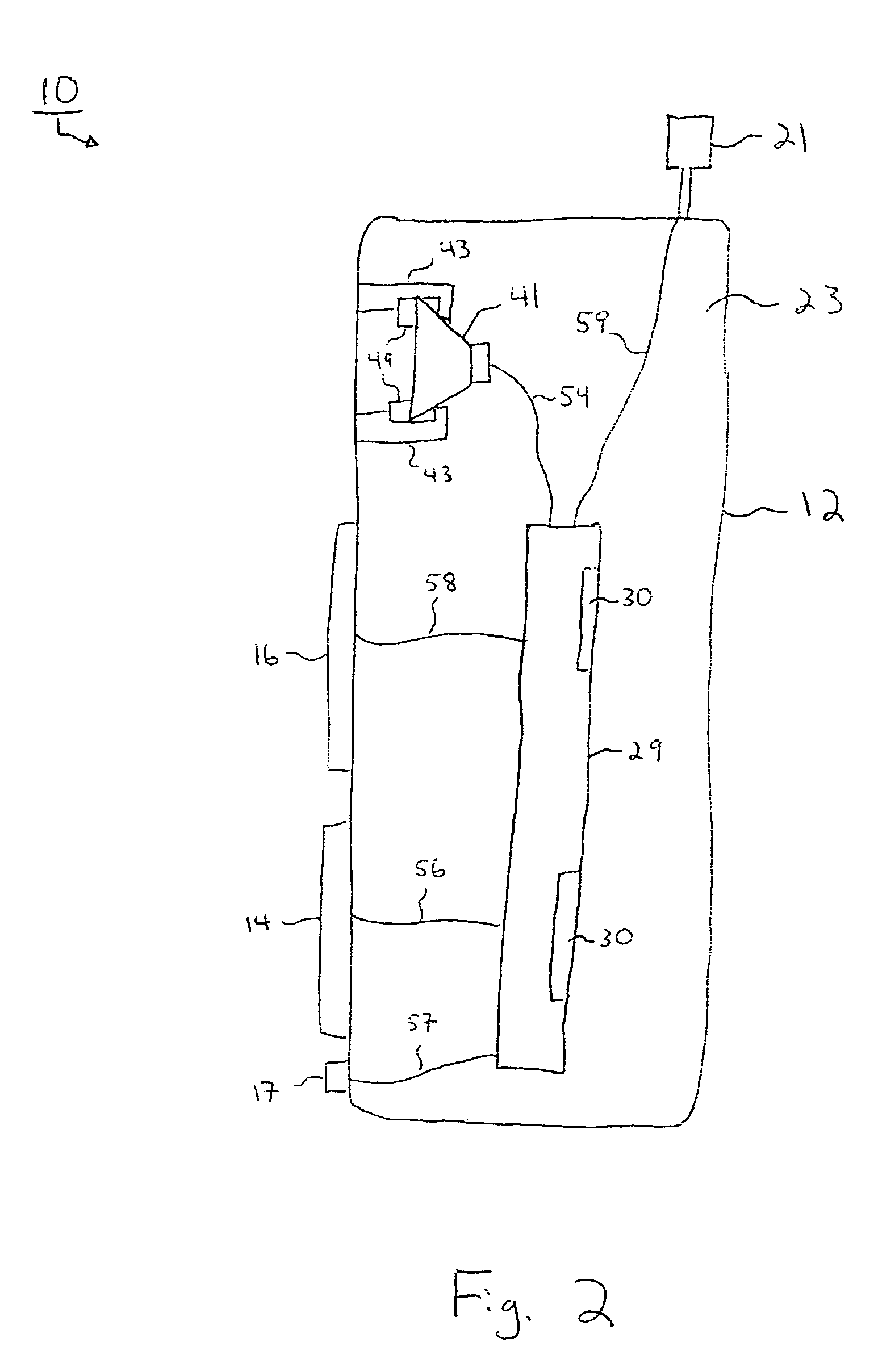
[0020]The wireless handset 10 includes a speaker 41 mounted to the housing 12. The speaker 41 is constructed to mechanically vibrate at a mechanical vibration resonant frequency when driven by a low frequency drive signal. The speaker 41 functions to generate audio signals and mechanical vibrations for the user. However, the mechanical vibration resonant frequency of the speaker 41 varies from speake...


PUM


Abstract

A mobile wireless communication device has a speaker that functions as a vibration alert in addition to an audio output device. The speaker is selected from a group of speakers having variation in mechanical vibration resonant frequency. A drive signal sweeps back and forth across a sweep frequency range including the varient speaker mechanical vibration resonant frequencies. The drive signal drives the speaker causing it to vibrate at the mechanical vibration resonant frequency and in turn causing the mobile wireless communication device to vibrate, thereby alerting the user. In this manner, the same drive signal can be used to vibrate each speaker at the speaker's mechanical vibration resonant frequency despite the variation in mechanical vibration resonant frequencies among the group of speakers.

Description

FIELD OF THE INVENTION[0001]This invention relates to a mobile wireless communication device. More particularly, the present invention relates to a new and improved mobile wireless communication device incorporating a method for alerting a user with a speaker vibration alert.BACKGROUND OF THE INVENTION[0002]Wireless mobile communications devices, such as a mobile handset, are widely popular. Such wireless devices often have a speaker for producing audio sounds. For example, the speaker can reproduce a caller's voice, generate ringing tone sounds, play music or facilitate hands-free device operation.[0003]Wireless mobile communications devices also may have a silent alert mechanism, such as a mechanical vibrator or flashing light. The silent alert quietly notifies the user of an event associated with the wireless mobile communication device. In this manner, the user is notified of the event while others situated nearby are not disturbed. For example, a mechanical vibrator silent aler...

Claims


Application Information

Patent Timeline
Patent Type & Authority Patents(United States)
IPC IPC(8): H03J7/32H04B1/08H04B1/38H04M1/00H04M19/04
CPCH04M19/04H04M19/047
Inventor HUGUNIN, DERICK
Owner KYOCERA CORP
Learn More