Rotary and mud-powered percussive drill bit assembly and method

a percussive drill and assembly technology, applied in the direction of drilling drives, rotary drilling, percussion drilling, etc., can solve the problems of affecting the integrity of the solid, affecting the drilling rate, and affecting the drilling speed of the drill bit, so as to achieve the effect of increasing the drilling ra

Inactive Publication Date: 2007-07-10
ENERGY TECH GROUP
View PDF29 Cites 54 Cited by
  • Summary
  • Abstract
  • Description
  • Claims
  • Application Information

AI Technical Summary

Benefits of technology

[0012]The primary object of the invention is to provide a method and apparatus that results in increased drilling rates.
[0013]Another object of the invention is to provide a drill bit assembly for which additional energy can be applied to the rock face (over what is being applied in the industry today) that results in a greater rate of penetration of the well bore and a concomitant reduction in well bore cost.
[0014]Another object of the invention is to provide a method and apparatus where, by increasing the energy level of the mud system to accommodate the piston mud engine of the invention, the drilling system is allowed to operate as before but with the added energy applied to the rock face that will aid in the penetration rate.
[0022]Another object of the invention is to provide a method and apparatus that aids and improves control of directional drilling.SUMMARY OF THE INVENTION
[0024]In a preferred embodiment, the method includes drilling a hole with a drill string including a generally conventional diamond drag-type or tricone drill bit that has a longitudinal passage formed therein for slideably housing at least a portion of an impact bit. The drill bit is connected to a drillpipe sub which houses a mud-powered impact engine for reciprocating the impact bit against the formation or for striking an anvil surface on the impact bit to aid in fracturing the formation. Power is provided to the impact engine using added or excess hydraulic power output of a mud system, by increasing its hydraulic power as needed, without disruption of the ordinary drilling setup.

Problems solved by technology

Under some circumstances, either plastic deformation or brittle fracture may occur alone, but both often occur together.
However, abrasive wear by plastic deformation also occurs when the flowing material forms a raised prow of material in front of the leading edge of the particle.
However, at load values above the critical value, the induced stresses cause a median vent crack to form perpendicular to the surface of the substrate from the bottom of the indention into the substrate.
These lateral vent cracks destroy the integrity of the solid and lead directly to the removal of material from the solid.
As the drill bit axially rotates in the bore under a longitudinal compressive load, the roller cones are forced to revolve around their axes causing the protuberances to rapidly impact the formation (abrasive wear by brittle fracture), but cone offset and friction in the roller cones under load also cause the protuberances to be dragged slightly across the formation for shearing (abrasive wear by plastic deformation).
Although such systems may use standard off-the-shelf drill bits, because the entire bit is impacted against the formation, the impact force is still spread across the large number of impact points resulting in only a fraction of the overall impact force acting at any given point in the formation.
Despite such advancements, even today conditions exist in the drilling of deep, horizontal, or high pressured wells where the rates of penetration are very low and the associated costs are high.

Method used


Image

  • Rotary and mud-powered percussive drill bit assembly and method
  • Rotary and mud-powered percussive drill bit assembly and method
  • Rotary and mud-powered percussive drill bit assembly and method

Examples


Embodiment Construction

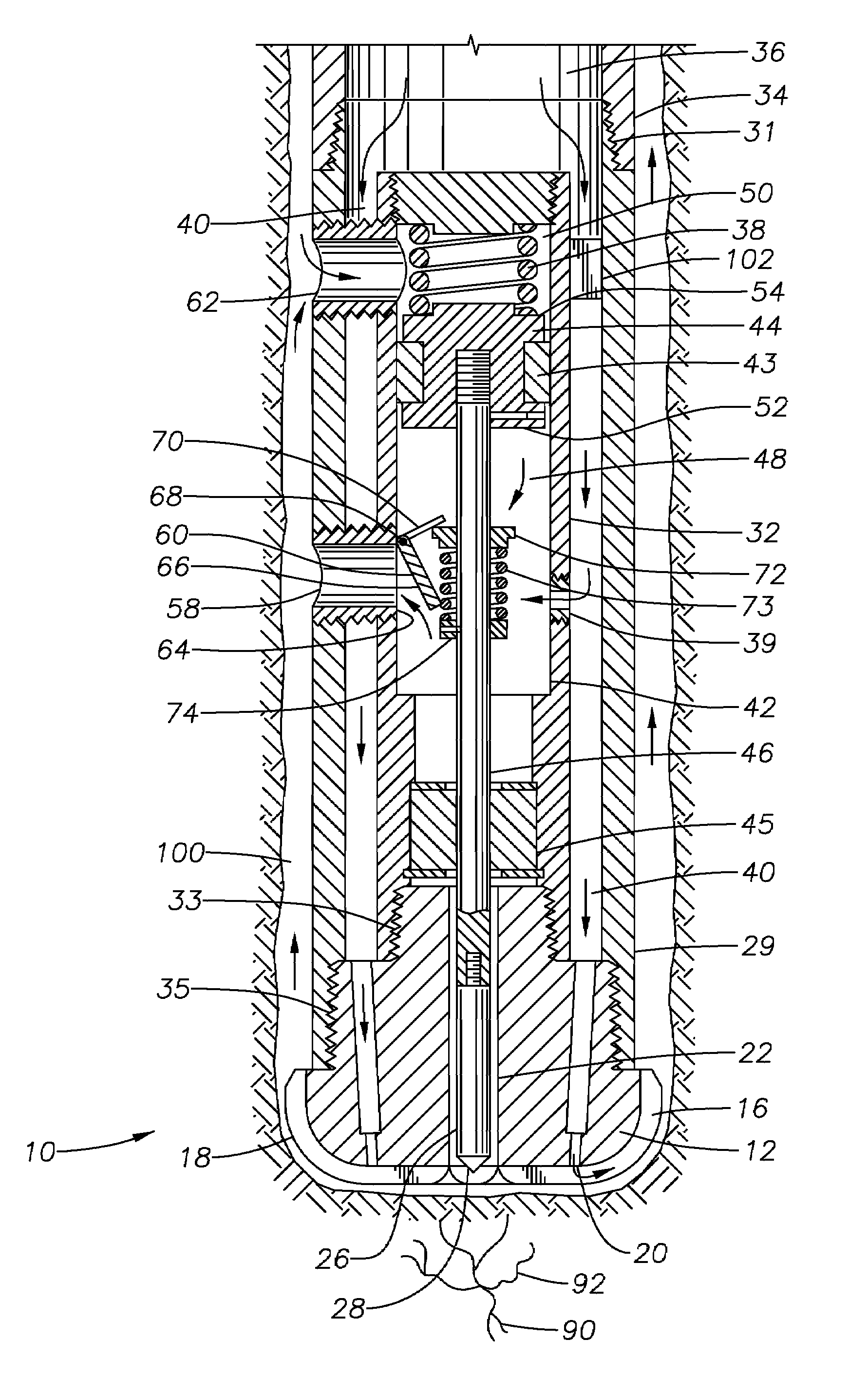
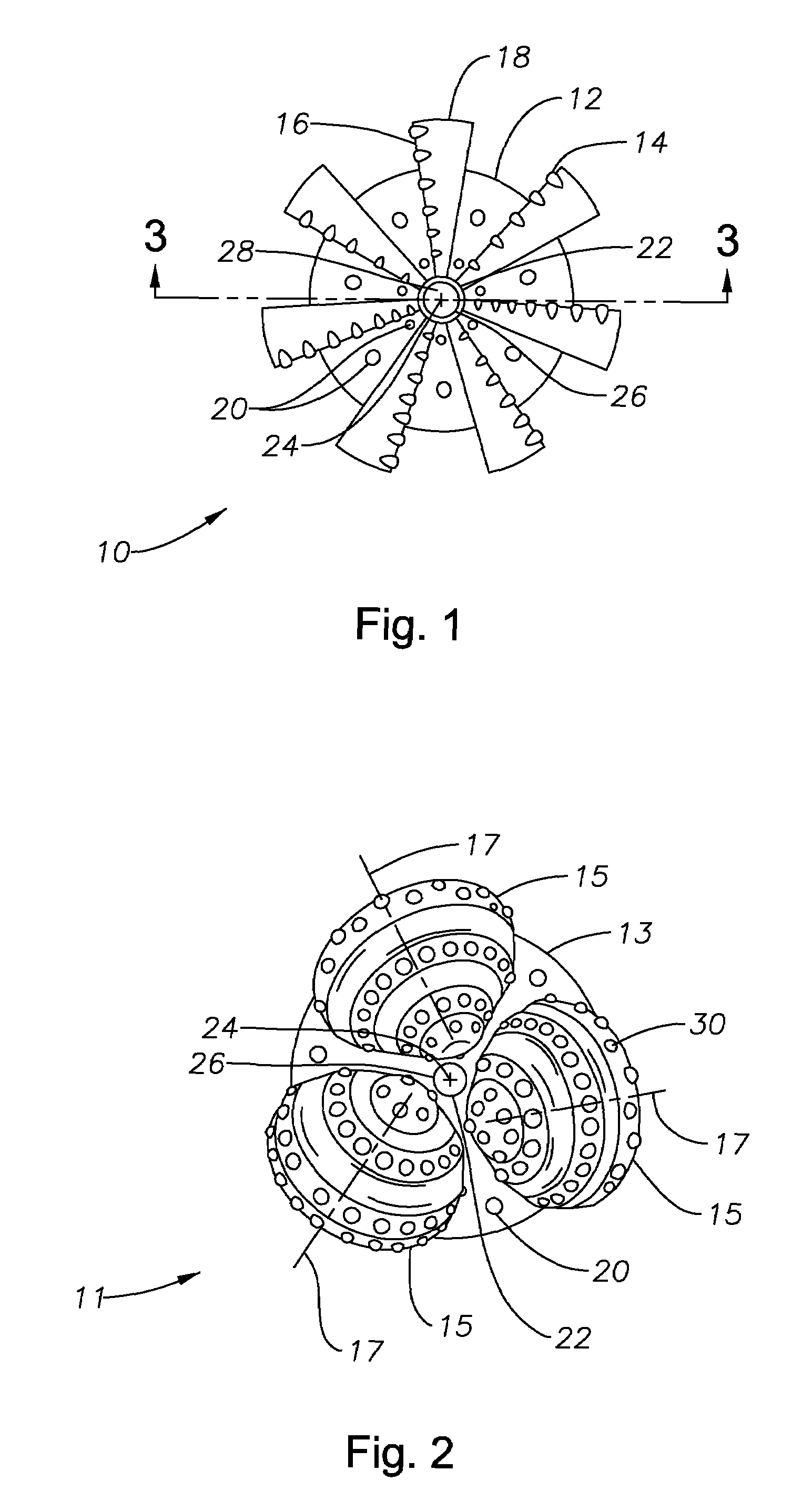
[0035]FIG. 1 illustrates the distal cutting end of a drill bit assembly 10 according to one embodiment of the invention. The drill bit assembly 10 preferably includes a drag-type drill bit 12 with hard cutters 14 pressed into the leading edges 16 of the flutes 18. The cutters 14 are preferably natural diamond or PDC, but other suitable materials may be used. Although seven straight flutes are shown, any suitable number of straight or curved flutes may be used. Drill bit 12 may include one or more nozzles 20 for jetting drilling fluid to aid in formation cutting, tool cooling, lubrication, and debris removal. The diameter of drill bit 12 is preferably suitable for boring a well of standard gauge.

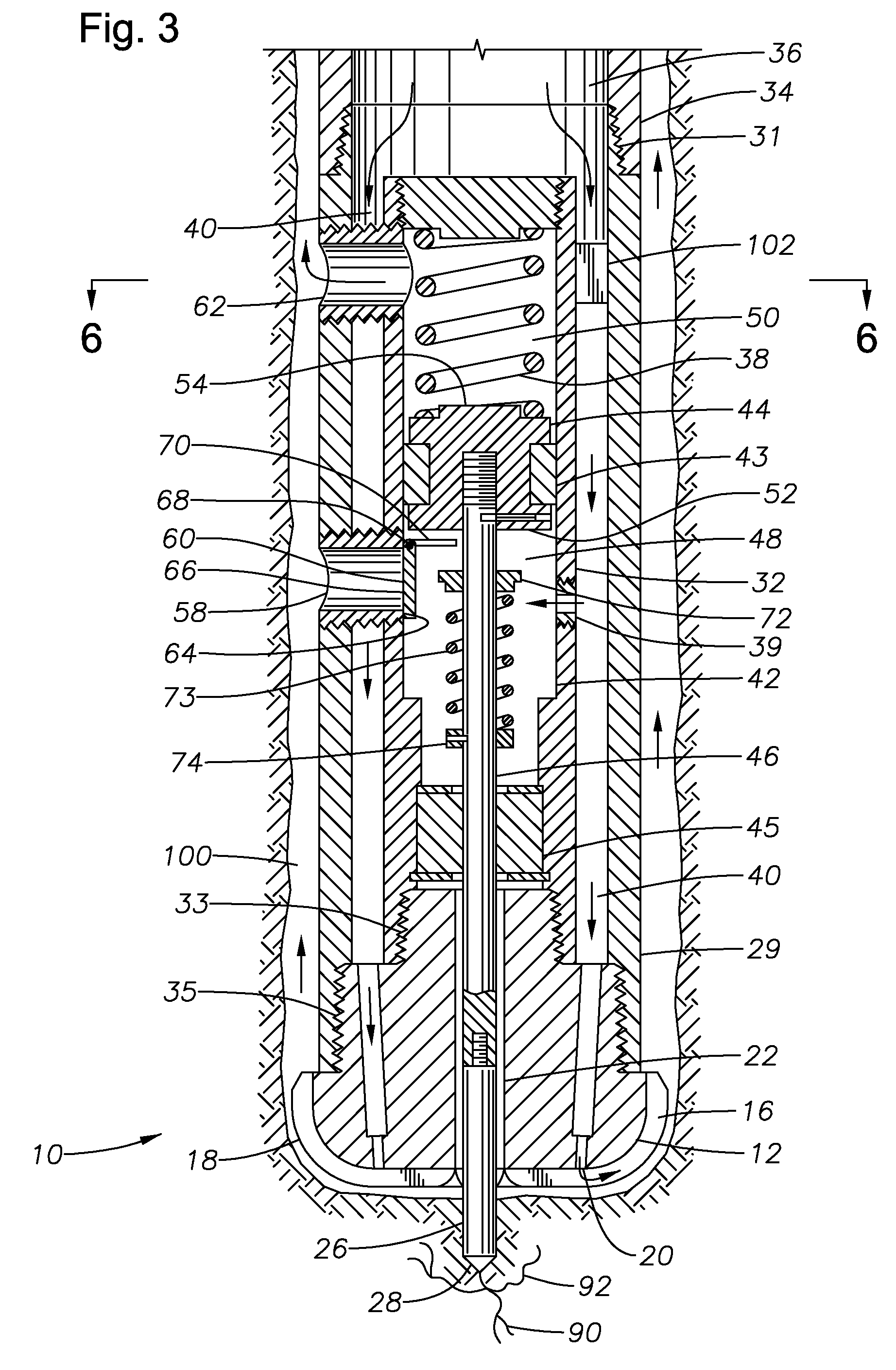
[0036]Drill bit 12 has a longitudinal passage 22 formed therein for slideably housing an impact bit 26. The longitudinal passage 22 and impact bit 26 are preferably centered at drill bit centerline 24, but they may also be located off center. Impact bit 26 is reciprocated longitudinally so th...


PUM


Abstract

A method and apparatus for boring a hole in the earth including a drill bit assembly including a fluid-powered impact engine contained within a drillpipe sub between an ordinary drillpipe and a modified conventional rotary drill bit. The impact engine is powered by pressurized drilling fluid delivered via the drillpipe which acts on a piston to charge an energy accumulator, preferably in the form of a spring. Periodically, the pressurized drilling fluid in the impact engine is vented, allowing the energy accumulator to rapidly transfer its stored energy to an impact bit which is slidingly housed in a rotary bit to strike and fracture the formation.

Description

BACKGROUND OF THE INVENTION[0001]1. Field of the Invention[0002]This invention relates generally to a method and apparatus for boring a hole in the earth and specifically to rotary and percussive drill bit assembly, which is preferably adapted for drilling wells for the hydrocarbon exploration and production industries but may be used for tunneling or similar applications.[0003]2. Description of the Prior Art[0004]The process of drilling a hole in the earth's crust involves abrasive wear of the formation, wherein earth is removed or displaced by hard particles or protuberances on a drill bit forced against or slid along the formation surface at the bore / formation interface. For a solid subjected to a uniaxial stress in the form of a point load (force), the observed behavior of the solid is usually perfect elastic deformation followed by irrecoverable distortion that may take the form of plastic flow or fracture. In other words, the abrasive wear generally occurs by two distinct mech...

Claims


Application Information

Patent Timeline
IPC IPC(8): E21B1/28
CPCE21B4/14E21B10/36
Inventor KEMICK, JEROME
Owner ENERGY TECH GROUP
Why Eureka
Try Eureka