
Storage media data structure system and method

a data structure and media technology, applied in the field of data storage, can solve the problems of fragmentation of allocated disc space, increase the complexity of allocating disc space to files, etc., and achieve the effects of reducing overhead, simple allocation overhead, and increasing data access rates

Active Publication Date: 2007-06-26
SEAGATE TECH LLC
View PDF36 Cites 53 Cited by
  • Summary
  • Abstract
  • Description
  • Claims
  • Application Information

AI Technical Summary

Benefits of technology

"The present invention provides a flexible and efficient way to store data in a virtual mapped storage system. It uses a plurality of grids with columns and rows to organize data blocks. Different versions of the data are applied to the grids to support different storage formats simultaneously. The data is organized in a reduced overhead format, allowing for easy allocation and conversion between formats. The invention also includes metadata that describes the data storage units and their relationships, as well as pointers to access specific units. The technical effects of the invention include improved data storage capacity, flexibility, and access speed."

Problems solved by technology

For example, physically mapped systems do not require the overhead of a lookup table or other data structure, but do not allow allocation of files such that access may be more evenly distributed across a number of drives for improved performance.
This can result in increased complexity in allocating disc space to files and in lookup table overhead and execution time in accessing files.
Conversion of files from a first storage format to a second storage format may require additional complexity in allocation routines and may result in fragmentation of allocated disc space.

Method used


Image

  • Storage media data structure system and method
  • Storage media data structure system and method
  • Storage media data structure system and method

Examples


Embodiment Construction

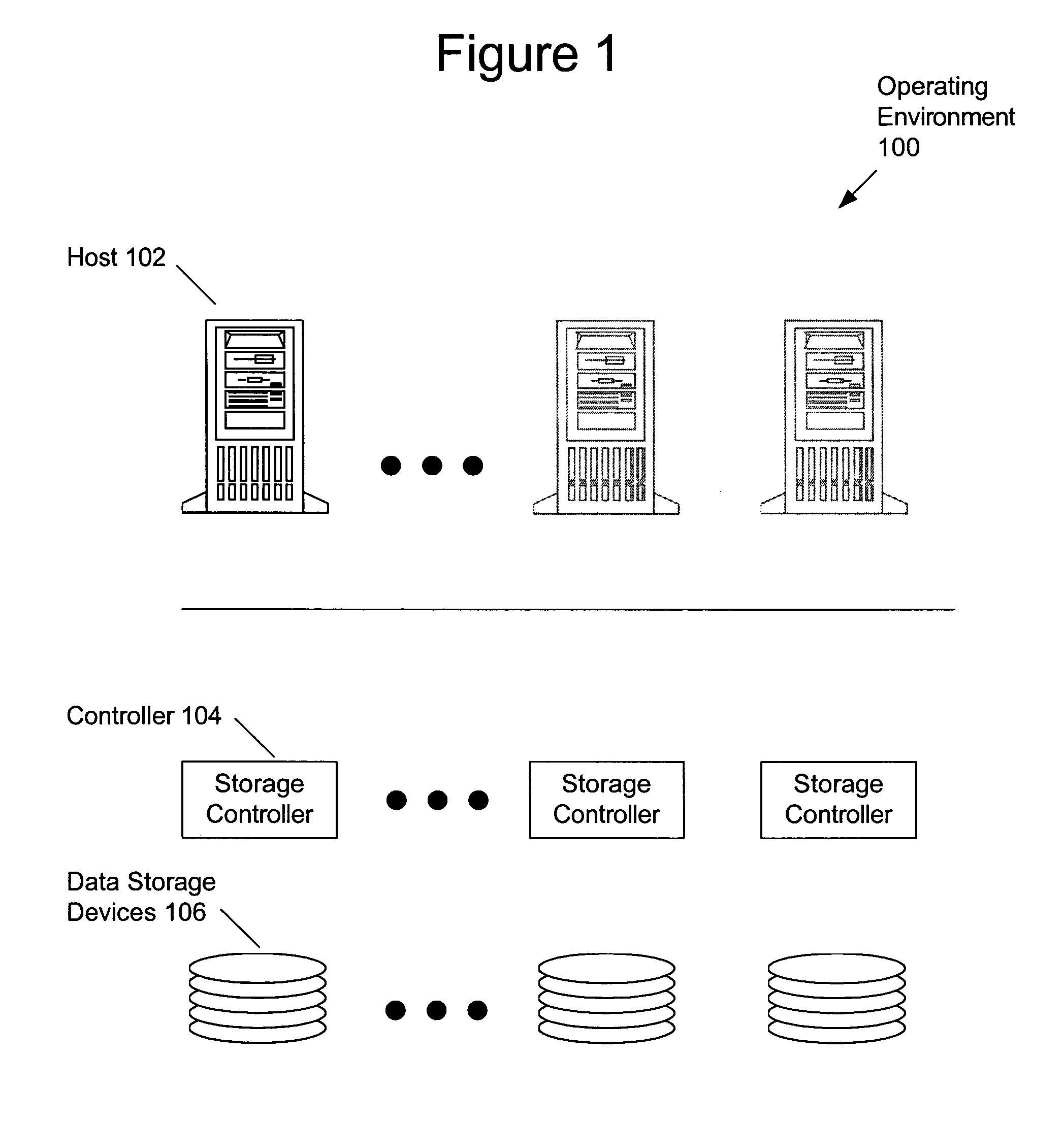
[0040]Embodiments of the present invention may be employed in various storage architectures and operating environments. These environments include storage arrays and may include associated host systems, interface controllers, disc controllers, and arrays of storage media. FIG. 1 depicts an operating environment 100 of embodiments of the present invention. One or more hosts 102 are coupled to one or more storage controllers 104 that provide access to a plurality of data storage devices 106. A plurality of arrays of data storage devices may be employed. Data storage devices may comprise disc drives, optical memories, semiconductor memories, or any other devices that store data. Computer program code operating in one or more host systems, storage controllers, interface controllers (not depicted) and / or data storage devices serves to implement the data structure system and method of embodiments of the present invention. Each data storage device may be considered a failure domain and, as...


PUM


Abstract

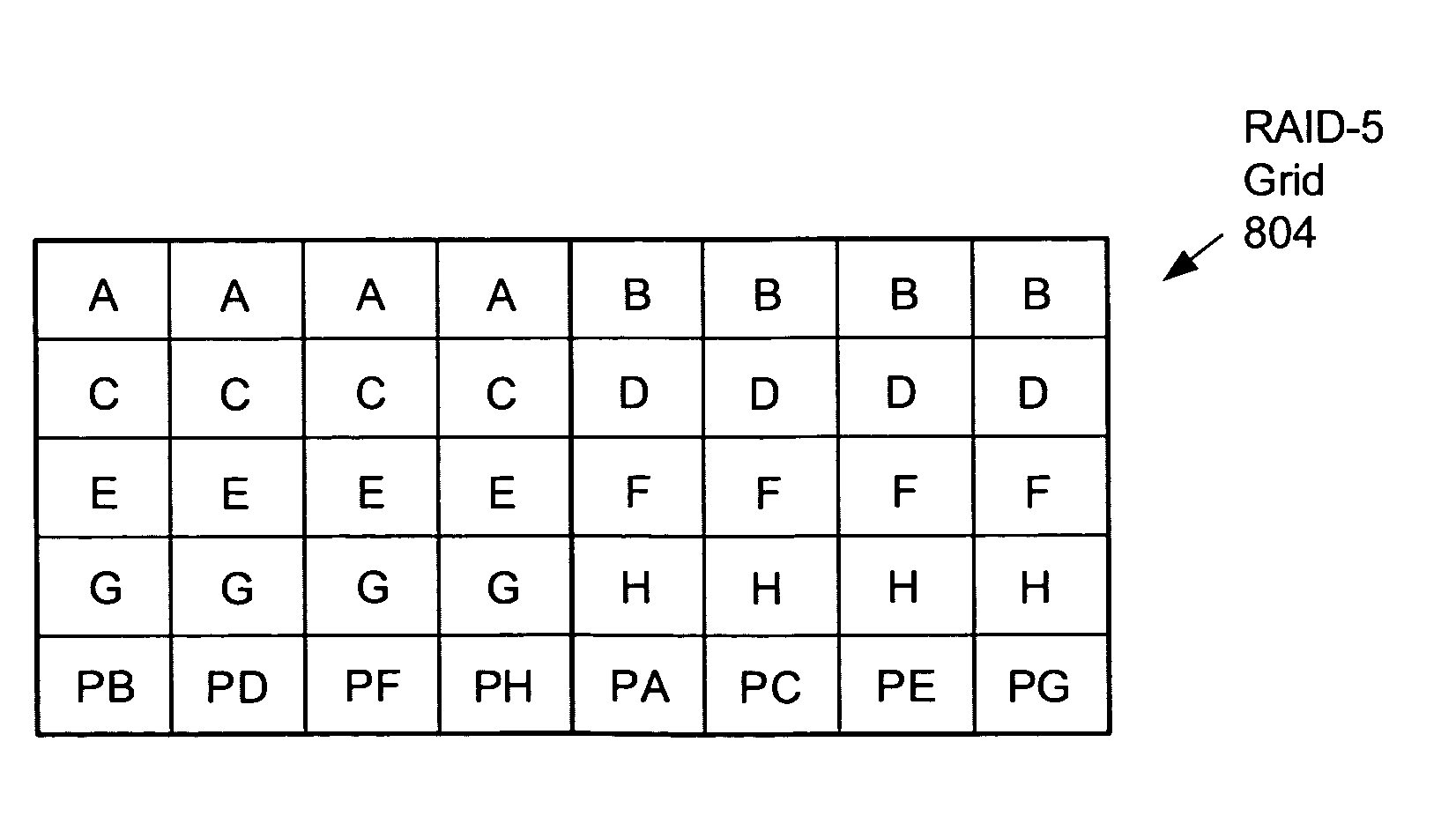
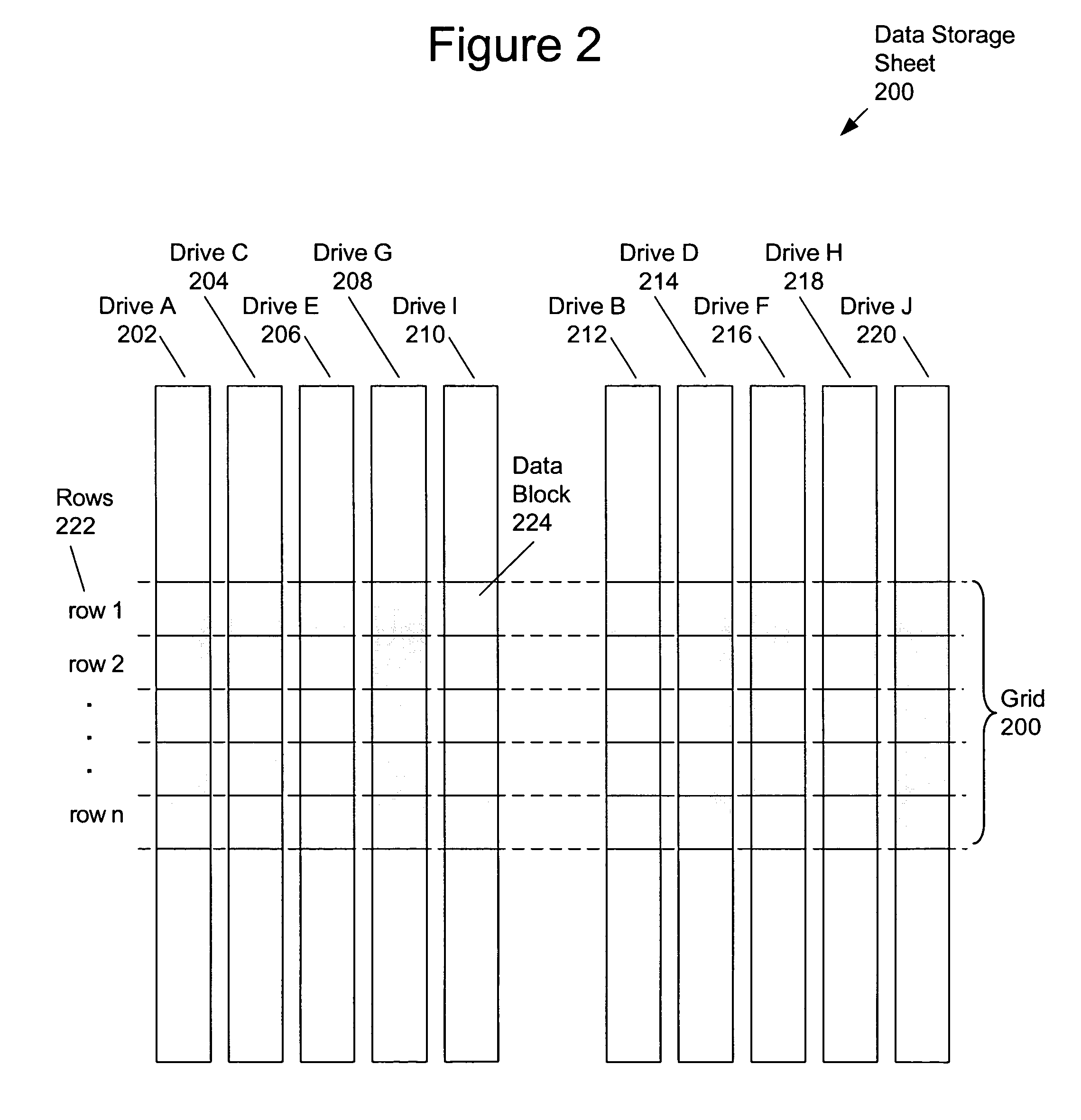
Disclosed is a data storage architecture employing a plurality of data grids each comprising an array of equal capacity data storage blocks organized into a plurality of rows and a plurality of columns such that each column corresponds to a storage domain in a data storage system and each row of the plurality of rows corresponds to a plurality of data storage blocks, one data storage block from each column of the plurality of columns at the same physical address, with the plurality of rows each having a plurality of contiguous data storage blocks in each domain. Capacity grids are produce by applying one of a plurality of sparing versions that designate at least one data storage block in each row of the grid is designated as spare, Defined within each capacity grid are one or more data storage units. Each data storage unit reflects a storage format, such as a RAID level, and defines data storage blocks, mirror data blocks, and parity data blocks depending upon storage the format and can provide fault tolerance in the event of a domain failure. User data is stored exclusively in a first portion of the grid and parity data, if any, is exclusively stored in a second portion of the grid, providing optimized performance. Data access employs metadata that may comprise grid and storage unit descriptors, data storage unit format, and a sparing table.

Description

BACKGROUND OF THE INVENTION[0001]a. Field of the Invention[0002]The present invention pertains generally to storage of data and more specifically to organization and management of data in fault tolerant data storage systems.[0003]b. Description of the Background[0004]Fault tolerant data storage systems may store data across a plurality of disc drives and may include duplicate data, parity or other information that may be employed to reconstruct data if a drive fails.[0005]Data storage systems may employ physical addressing or virtual addressing methods. In physical addressing, a file address specifies a physical address in the storage system. In virtual addressing, a file address is an address applied to a lookup table or other metadata structure to provide an actual physical address by providing an association of the virtual file address with the physical address.[0006]Physical addressing and virtual addressing methods have both benefits and disadvantages. For example, physically m...

Claims


Application Information

Patent Timeline
Patent Type & Authority Patents(United States)
IPC IPC(8): G06F12/00
CPCG06F3/0619G06F3/0638G06F3/0683G06F2211/1028
Inventor LUBBERS, CLARK E.ROBERSON, RANDY L.
Owner SEAGATE TECH LLC
Learn More