
Method for setting erasing pulses and screening erasing defects of nonvolatile memory

a nonvolatile memory and pulse technology, applied in static storage, digital storage, instruments, etc., can solve the problems of increasing the number of memory cells at lower threshold voltages, allowing unselected memory cells to be read out, and hardly determining the readout current at the memory cells

Active Publication Date: 2007-06-26
SAMSUNG ELECTRONICS CO LTD
View PDF4 Cites 5 Cited by
  • Summary
  • Abstract
  • Description
  • Claims
  • Application Information

AI Technical Summary

Benefits of technology

The present invention provides a method for setting erasing pulses for nonvolatile memory that can determine the number of or time for applications of erasing pulses in a block erasing operation. This method can effectively detect and screen out slowly erased bits in a normal distribution. By applying the ideal number of erasing pulses and minimizing the time required for erase verification, the method contributes to the speeding up of the erasing operation.

Problems solved by technology

When the threshold voltage in the memory cells is too low, it may increase leaks during the readout operation from unselected memory cells connected to the common bit lines, whereby the readout current at the memory cells will hardly be determined (erroneous readout).
This will increase the number of memory cells at lower levels of the threshold voltage, permitting the unselected memory cells to be read out with difficulty due to the occurrence of off-leak currents.
However, the erasing operation depends largely on and may be disturbed in the characteristics by the effect of variations in the factors at the manufacturing process which include the tunnel oxide layer thickness, the coupling rate of the floating gate, and the threshold voltage at the erasing operation with ultraviolet ray.
It will be very difficult for conducting the erasing operation with a margin not to over-kill the normal distribution because the variations declining the accuracy are eliminated only at the area denoted by (d) in FIG. 5.
Also, as the width (e) of the distribution of the threshold voltages shown in FIG. 4 is varied during the manufacturing process, it will additionally decline the accuracy.

Method used


Image

  • Method for setting erasing pulses and screening erasing defects of nonvolatile memory
  • Method for setting erasing pulses and screening erasing defects of nonvolatile memory
  • Method for setting erasing pulses and screening erasing defects of nonvolatile memory

Examples


Embodiment Construction

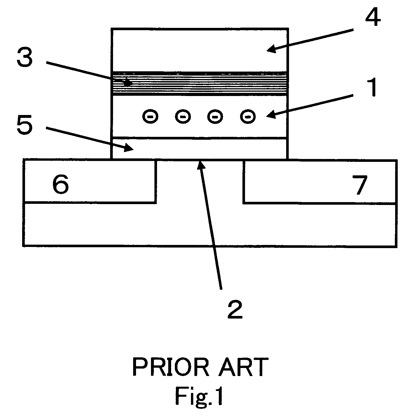
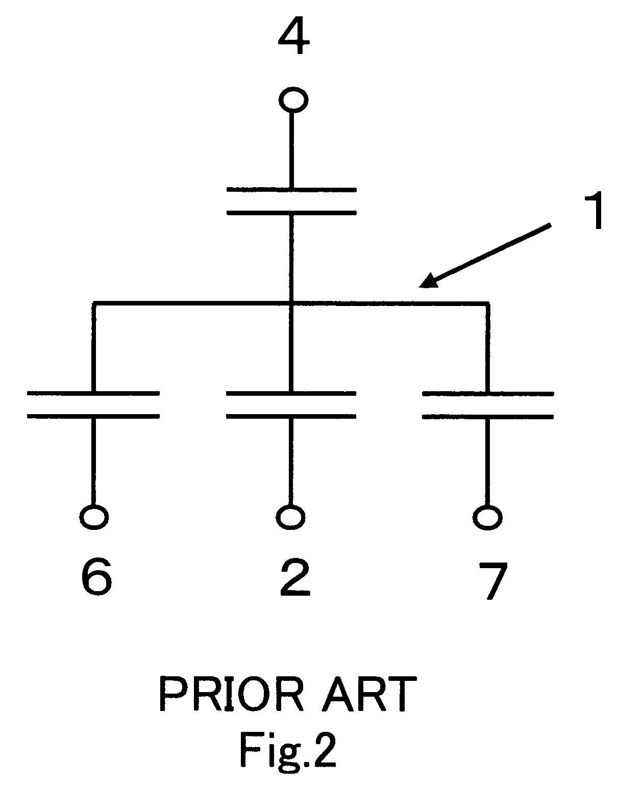
[0034]Embodiments of a method for setting erasing pulse and an erasing defect screening method according to the present invention (referred to as a “setting method of the present invention” and a “screening method of the present invention” hereinafter) will be described referring the relevant drawings.

[0035]A nonvolatile memory subjected to the setting method and the screening method of the present invention comprises, similar to a conventional flash memory, a memory cell array having an array of flash memory cells provided of a memory cell structure identical to that shown in FIG. 1 and a memory array control circuit including an address decoder, a voltage generation circuit, a timing control circuit, a sense amplifier and the like for conducting the memory operations (programming, erasing, reading) on each memory cell in the memory cell array. The erasing operation involves applying erasing pulses plural times to a block of the memory cells to be erased so that electrons can be re...


PUM


Abstract

Method for determining the number of applications of erasing pulses, including extracting two pairs of the accumulated number of the erasing pulses Np and the ratio Re of the number of erased memory cells in the target block to be erased after the accumulated number of the erasing pulses Np has been applied, converting the two ratios Re into normalized variables S(Re) through normalizing the random variables of the normal distribution probability with standard deviations, converting the two accumulated numbers of the erasing pulses Np into common logarithms Log(Np), calculating a common logarithm Log(Nt) through extrapolating from two sets of coordinates [Log(Np), S(Re)], and determining the number of applications of the remaining erasing pulses so that the extrapolation erasing pulse number Nt is the target accumulated number of applications of erasing pulses.

Description

CROSS REFERENCE TO RELATED APPLICATION[0001]This Nonprovisional application claims priority under 35 U.S.C. §119(a) on Patent Application No. 2004-299574 filed in Japan on Oct. 14, 2004, the entire contents of which are hereby incorporated by reference.BACKGROUND OF THE INVENTION[0002]1. Field of the Invention[0003]The present invention relates to a method for setting erasing pulse determining the number of or time for applications of the erasing pulses in a block erasing operation where a target block which consists mainly of a number of memory cells to be erased in a nonvolatile memory is erased by applying the erasing pulses plural times for erasing its block data together. Also, the present invention relates to a method for screening erasing defects in the nonvolatile memory and, more particularly, to a screening method capable of specifying defective memory cells which are slower in the erasing operation than the normally erased memory cells.[0004]2. Description of the Related ...

Claims


Application Information

Patent Timeline
Patent Type & Authority Patents(United States)
IPC IPC(8): G11C11/34G11C16/04
CPCG11C16/16G11C16/344G11C16/3445G11C16/349
Inventor UEDA, NAOKI
Owner SAMSUNG ELECTRONICS CO LTD
Learn More