
Methods for evaluating cutting arrangements for drill bits and their application to roller cone drill bit designs

a cutting arrangement and drill bit technology, applied in the field of drill bits, can solve the problems of poor drilling performance of cone drill bits, waste of energy, inefficient tracking, etc., and achieve the effect of different measuremen

Active Publication Date: 2007-06-26
SMITH INT INC
View PDF16 Cites 40 Cited by
  • Summary
  • Abstract
  • Description
  • Claims
  • Application Information

AI Technical Summary

Benefits of technology

[0014]In one or more embodiments, a method for evaluating a cutting arrangement for a drill bit includes selecting a cutting element arrangement for the drill bit and calculating a score for the cutting element arrangement.
[0015]In one or more embodiments, a method for designing a drill bit includes selecting an arrangement of cutting elements for the drill bit. The arrangement includes at least a number of cutting elements and spaces between the cutting elements. The method also includes calculating a score for the arrangement based on the number of cutting elements and the spaces between cutting elements.
[0016]In one or more embodiments, a method for optimizing a cutting arrangement for a drill bit includes selecting an arrangement of cutting elements for the drill bit, calculating a score for the arrangement, adjusting at least one parameter of the arrangement and calculating a score for the adjusted arrangement. The adjusting of the arrangement and the calculating of a score for the adjusted arrangement are repeated until a desired score is obtained. In one or more embodiments, the adjusting and the calculating a score are repeated for each of a number of arrangements and an optimized arrangement is determined as the arrangement having the most favorable score.
[0017]In one or more embodiments, a method for optimizing a cutting arrangement for a drill bit includes: (a) selecting an arrangement of cutting elements for the drill bit, (b) determining a bottomhole hit pattern for the arrangement, and (c) comparing the bottomhole hit pattern to a preferred hit pattern. The method also includes: (d) adjusting at least one parameter of the arrangement, and (e) repeating steps (b) through (d) until a preferred arrangement having a bottomhole hit pattern similar to the preferred hit pattern is obtained.
[0018]In one or more embodiments, a method for evaluating a cutting efficiency of a roller cone drill bit in drilling on a bottomhole includes selecting an arrangement of cutting elements on at least one cone of the roller cone drill bit. The arrangement includes at least a number of cutting elements and spaces between the cutting elements. The method also includes selecting evaluation parameters including at least a number of revolutions of the bit to be considered, and selecting a cone to bit rotation ratio. The method further includes determining for the arrangement, actual locations for hits of the cutting elements on the bottomhole when the roller cone drill bit is rotated by the number of revolutions on the bottomhole. The actual locations are determined based on the number of cutting elements, the spaces between cutting elements, and the rotation ratio. The method further includes calculating preferred locations for hits on the bottomhole based on the number of actual locations of hits made on the bottomhole. The method also includes calculating a score for the arrangement based on a comparison between the actual locations and the preferred locations.
[0019]In one or more embodiments, a roller cone drill bit in accordance with an aspect of the invention includes a plurality of roller cones adapted to roll on a bottomhole surface and a plurality of cutting elements generally arranged in a row on at least one of the roller cones. The plurality of cutting elements are arranged with spaces in between them such that a first group of contiguous spaces, which includes at least three spaces, are all substantially equal in measurement to one another, and a second group of different contiguous spaces, which include at least two spaces, are all substantially equal in measurement to each other and are substantially different in measurement than the spaces in the first group.

Problems solved by technology

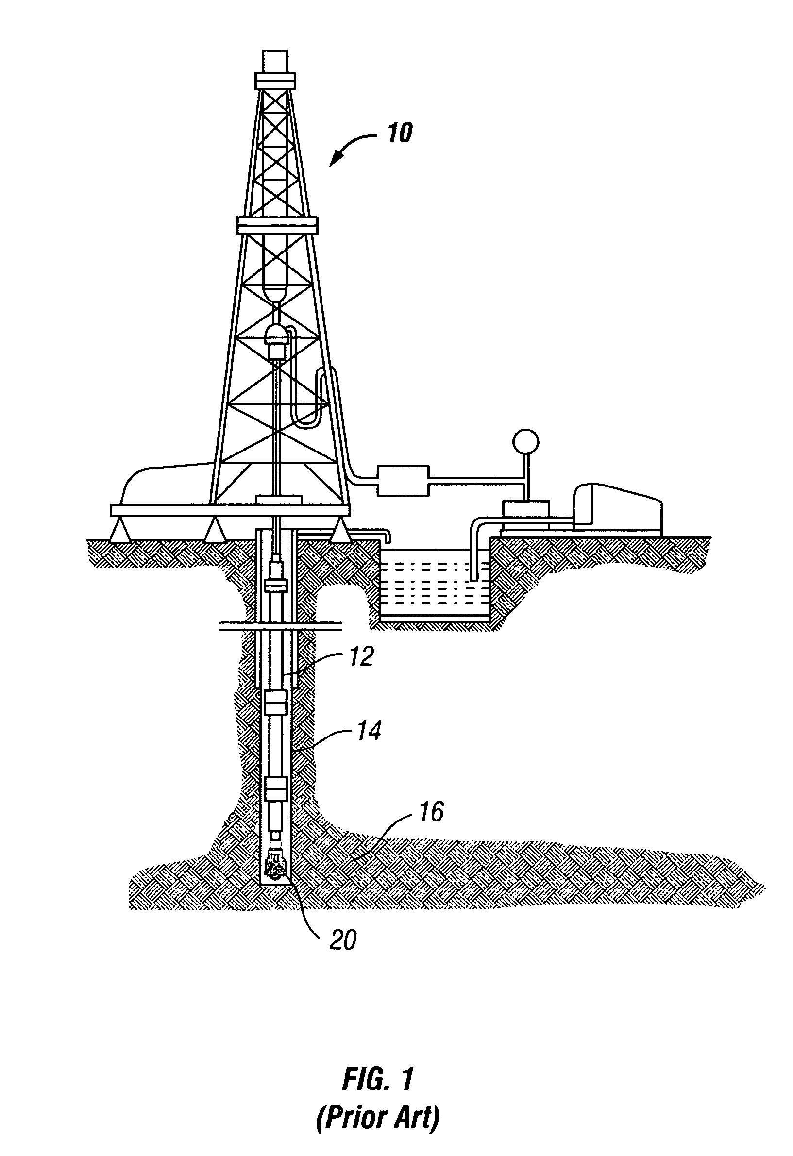
Many prior art roller cone drill bits have been found to provide poor drilling performance due to problems such as “tracking” and “slipping.” Tracking occurs when cutting elements on a drill bit fall into previous impressions formed in the formation by cutting elements at a preceding moment in time during revolution of the drill bit.
In particular, tracking is inefficient since there is no fresh rock cut, and thus a waste of energy.
Additionally, slipping should also be avoided because it can result in uneven wear on the cutting elements which can result in premature failure.
It has been found that tracking and slipping often occur due to a less than optimum spacing of cutting elements on the bit.
The problem in these design approaches is that the resulting arrangements are often arrived at somewhat arbitrarily, which can be time consuming in the evolution of the bit design and may or may not lead to drill bits producing desired drilling characteristics.

Method used


Image

  • Methods for evaluating cutting arrangements for drill bits and their application to roller cone drill bit designs
  • Methods for evaluating cutting arrangements for drill bits and their application to roller cone drill bit designs
  • Methods for evaluating cutting arrangements for drill bits and their application to roller cone drill bit designs

Examples


Embodiment Construction

[0039]The present invention relates to drill bits for drilling bore holes through earth formations. More particularly, the present invention provides a method for scoring a drill bit, a method for evaluating a cutting arrangement for a drill bit, a method for designing a drill bit, and a method for optimizing a cutting arrangement for a drill bit. In another aspect, the invention provides an improved cutting arrangement for a roller cone drill bit.

[0040]A flow chart showing one example of a method for scoring a drill bit in accordance with the present invention is shown in FIG. 7. This method may also be adapted and used to evaluate a cutting arrangement for a drill bit or to optimize a cutting arrangement on a drill bit. The method includes selecting a cutting arrangement for a drill bit 101 and determining at least one characteristic representative of drilling for the cutting arrangement on the drill bit 103. The method also includes selecting a criterion for evaluating the at lea...


PUM


Abstract

A method for evaluating a cutting arrangement for a drill bit includes selecting a cutting element arrangement for the drill bit and calculating a score for the cutting arrangement. This method may be used to evaluate the cutting efficiency of various drill bit designs. In one example, this method is used to calculate a score for an arrangement based on a comparison of an expected bottomhole pattern for the arrangement with a preferred bottomhole pattern. The use of this method has lead to roller cone drill bit designs that exhibit reduce tracking over prior art bits.

Description

CROSS-REFERENCE TO RELATED APPLICATIONS[0001]This application claims the benefit under 35 U.S.C. §119(e) of U.S. Provisional Patent Application No. 60 / 473,552, filed on May 27, 2003, titled “Methods for Designing, Evaluating, and Optimizing, Cutting Arrangements for Drill Bits and Their Application to Roller Cone Drill Bit Designs,” and now incorporated by reference.STATEMENT REGARDING FEDERALLY SPONSORED RESEARCH OR DEVELOPMENT[0002]Not applicable.COPYRIGHT OR MASK WORK NOTICE[0003]A portion of the disclosure of this patent document contains material which is subject to (copyright or mask work) protection. The (copyright or mask work) owner has no objection to the facsimile reproduction by anyone of the patent document or the patent disclosure, as it appears in the Patent and Trademark Office patent file or records, but otherwise reserves all (copyright or mask work) rights whatsoever.BACKGROUND OF INVENTION[0004]1. Field of the Invention[0005]The invention relates generally to dri...

Claims


Application Information

Patent Timeline
Patent Type & Authority Patents(United States)
IPC IPC(8): E21B10/16E21B10/00E21B41/00G06F17/50G06G7/48
CPCE21B10/00E21B10/16E21B10/52
Inventor MCDONOUGH, SCOTT D.SINGH, AMARDEEPBRIETZKE, DANIEL W.
Owner SMITH INT INC
Learn More