Eureka AIR delivers breakthrough ideas for toughest innovation challenges, trusted by R&D personnel around the world.

Food warming apparatus and method

a technology for heating apparatus and food, applied in the field of ovens, can solve the problems of limiting the effectiveness of this technology for holding applications, loss of flavor, and certain equipment, and achieve the effect of enhancing food quality

Inactive Publication Date: 2007-06-05
DUKE MANUFACTURING COMPANY
View PDF72 Cites 85 Cited by
  • Summary
  • Abstract
  • Description
  • Claims
  • Application Information

AI Technical Summary

Benefits of technology

[0006]Among the several objects of this invention will be noted the provision of an oven which is adapted for holding food longer without degradation of the quality of the product, including products having a crust which tends to become soggy or rubbery, such as fried potato products, fried chicken, and rotisserie chicken; and the provision of such an oven which allows evaporative losses to be more closely controlled to enhance food quality.

Problems solved by technology

However, such equipment has certain disadvantages.
For example, short holding times (e.g., one hour or less) and rapid product quality degradation often limit the effectiveness of this technology for holding applications.
As the food loses moisture due to evaporation, flavor is lost.
This affects the texture and taste of the product.
For example, chicken meat fibers will dry out and become tough, while the breading will become dry and greasy.
French fries will develop a dry, rubbery texture as moisture is lost and the outer skin loses its crispness.
Traditional IR holding devices cannot be adjusted to control the amount of IR energy delivered to the food and require a large amount of space since the IR heat source is in a fixed position relative to the food product.

Method used


Image

  • Food warming apparatus and method
  • Food warming apparatus and method
  • Food warming apparatus and method

Examples


example 1

Fried Chicken Nuggets

[0058]

Ambient hold time delay (B) =10 minutesHold temperature (T) =180° F.Time-base of duty cycle (G) =120 secondsPercent on time (E) =50%Total hold time (D) =60 minutes

example 2

Fried Apple Turnover

[0059]

Ambient hold time delay (B) = 25 minutesHold temperature (T) =200° F.Time base of duty cycle (G) =120 secondsPercent on time (E) = 40%Total hold time (D) =240 minutes

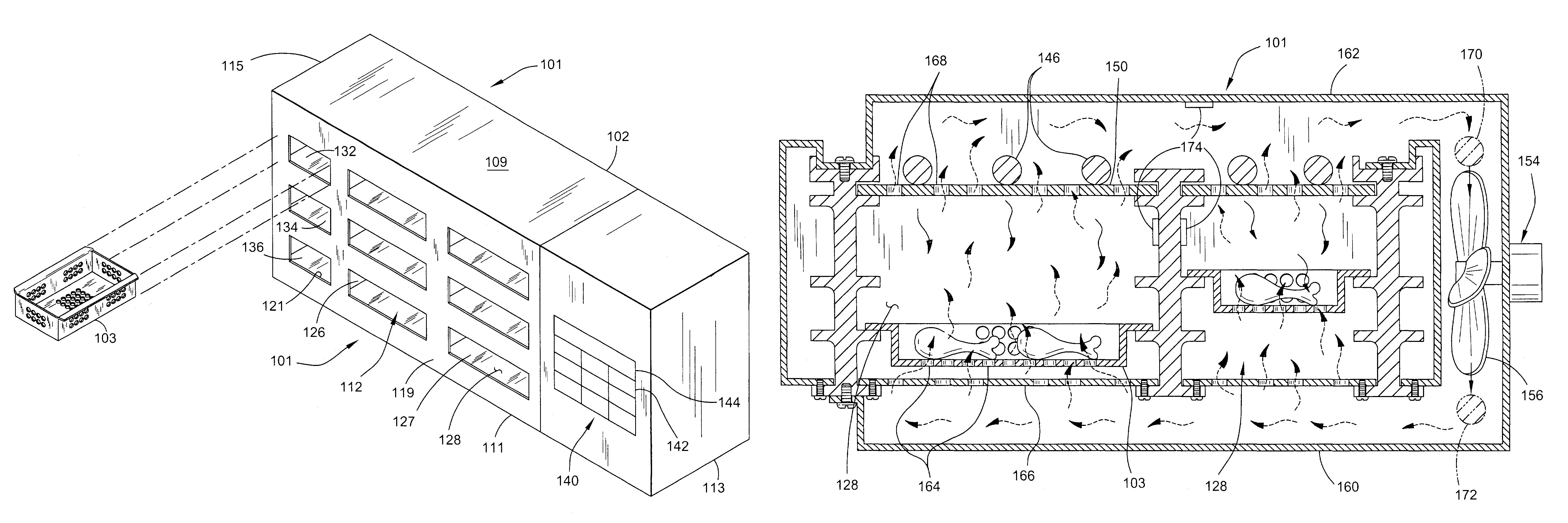
[0060]FIGS. 14 and 15 illustrate an example of the operation of the oven 101 in the second (heat up and hold or rethermalizing) mode. In particular, FIG. 14 illustrates a time vs. temperature curve for a complete hold cycle D for one compartment 128 of the oven 101, and FIG. 15 illustrates a time vs. activation curve for the heat source 146 of that same compartment during the hold cycle D. The time vs. temperature curve of FIG. 14 plots the temperature of the food product as a function of time. One skilled in the art will understand that this curve can be different for each type of food product to be held in the oven 101.

[0061]In this mode, the oven 101 is used to raise the temperature of a food product to a selected temperature and hold the food product at the selected temperature. A tray 103...

example 3

Diced Frozen Chicken

[0063]

Rethermalization time (I) = 40 minutesHold temperature (T) =220° F.Time-base of duty cycle (G) =180 secondsPercent on time (E) = 50%Total hold time (D) =160 minutes


PUM


Abstract

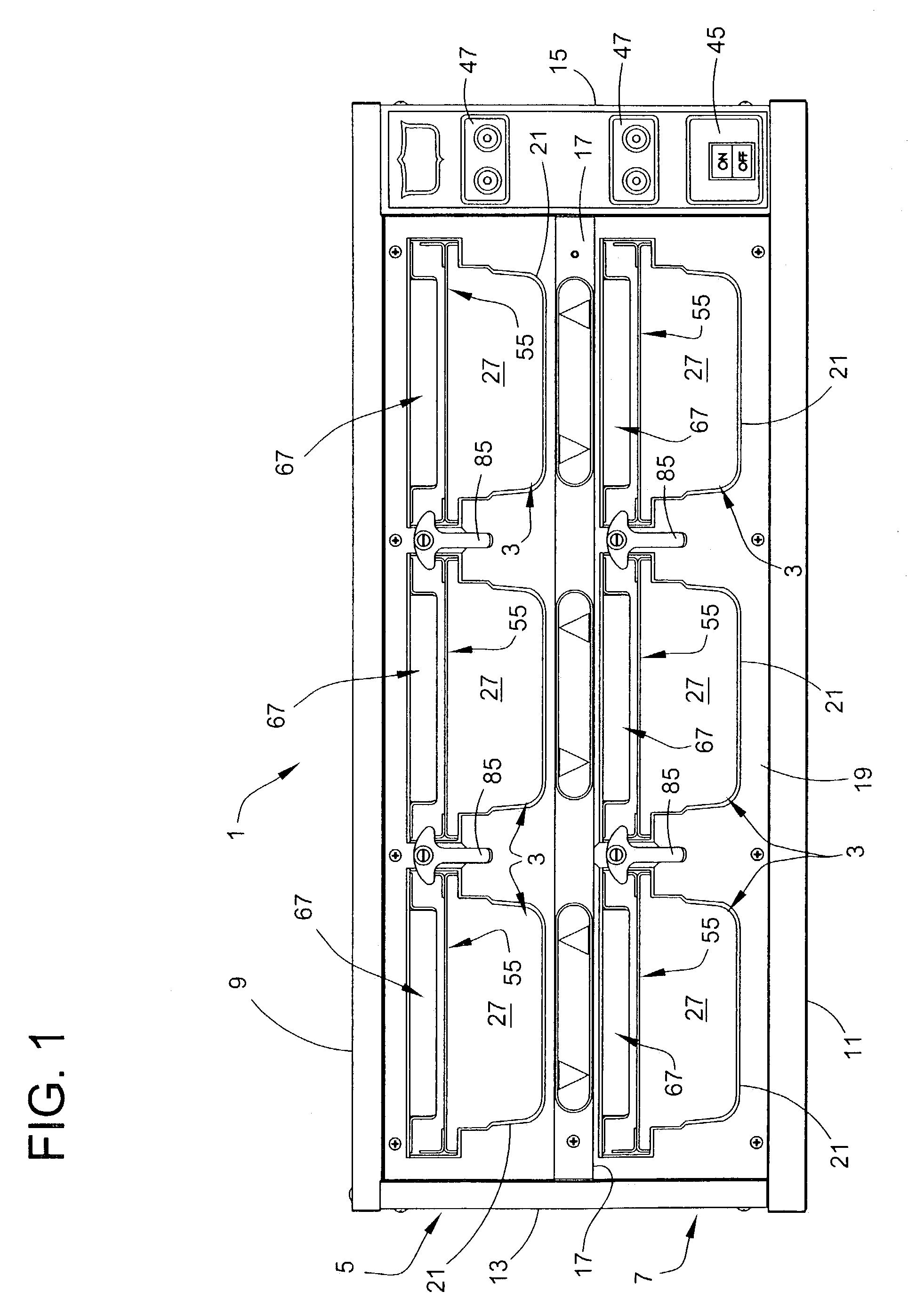
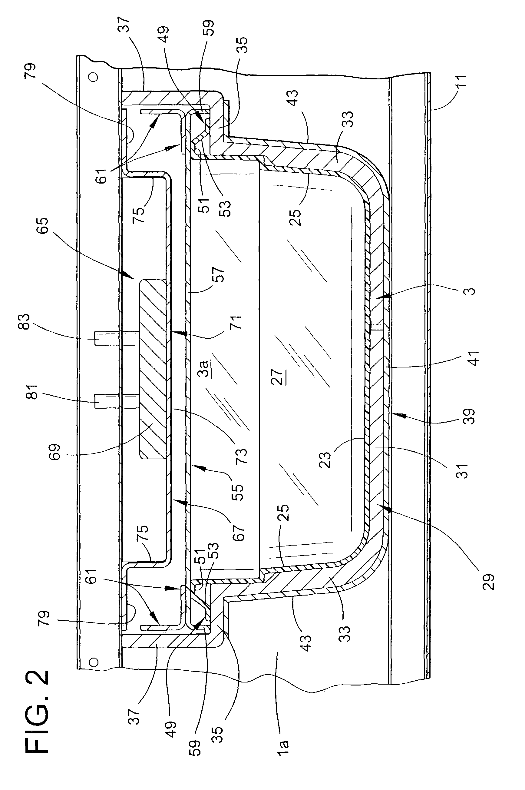
An oven for transferring heat to food in trays and a method for using the oven. The oven includes a cabinet with partitions dividing the interior into a plurality of separate, thermally isolated holding compartments each adapted for removably receiving a tray of food. Heat sources above the tray emit radiant heat to warm the food in the trays. A control mechanism controls the duration of the total hold time for the food having a duration of heated holding time during which a respective heat source is activated. The oven also includes a forced air mechanism under the control of the control mechanism for delivering forced air into the compartments. The heat sources are activated and deactivated during successive duty cycles to thereby to maintain the food in a respective compartment at a selected holding temperature for a duration of heated holding time.

Description

CROSS REFERENCE TO RELATED APPLICATION[0001]This application claims the benefit of U.S. Provisional Application No. 60 / 394,841, filed Jul. 10, 2002, titled HOLDING OR COOKING OVEN.BACKGROUND OF THE INVENTION[0002]This invention relates generally to ovens and more particularly to an oven for maintaining foods at temperatures suitable for serving or even for cooking food.[0003]In one embodiment, this invention is especially (but not exclusively) directed to food service equipment that uses infrared (IR) heaters to maintain food at proper temperatures before serving, and even for cooking food. Such technology is often used in, for example, the fast food service industry to heat food. However, such equipment has certain disadvantages. For example, short holding times (e.g., one hour or less) and rapid product quality degradation often limit the effectiveness of this technology for holding applications. Additionally, different food products require different amounts of IR energy to be he...

Claims


Application Information

Patent Timeline
IPC IPC(8): F24C7/04A47J36/24F27B5/02F24C1/00A21B1/26A23L1/00A47J9/00A47J27/14A47J39/00A47J39/02F24C7/06F24C7/08F24C15/16F27DF27D1/00
CPCA47J39/006F24C7/06F24C7/087F24C15/325
Inventor SHEI, STEVEN M.
Owner DUKE MANUFACTURING COMPANY
Why Eureka
Eureka Blog
Learn More