
Microwave burning furnace including heating element having two types of materials

a technology of heating element and microwave, which is applied in the direction of furnaces, lighting and heating apparatus, electric/magnetic/electromagnetic heating, etc., can solve the problems of prone to crack generation, and increasing the amount of an energy required for burning, etc., to achieve fastening a rise in ambient temperature, high energy efficiency, and high energy efficiency

Inactive Publication Date: 2007-05-29
PANASONIC CORP +1
View PDF8 Cites 3 Cited by
  • Summary
  • Abstract
  • Description
  • Claims
  • Application Information

AI Technical Summary

Benefits of technology

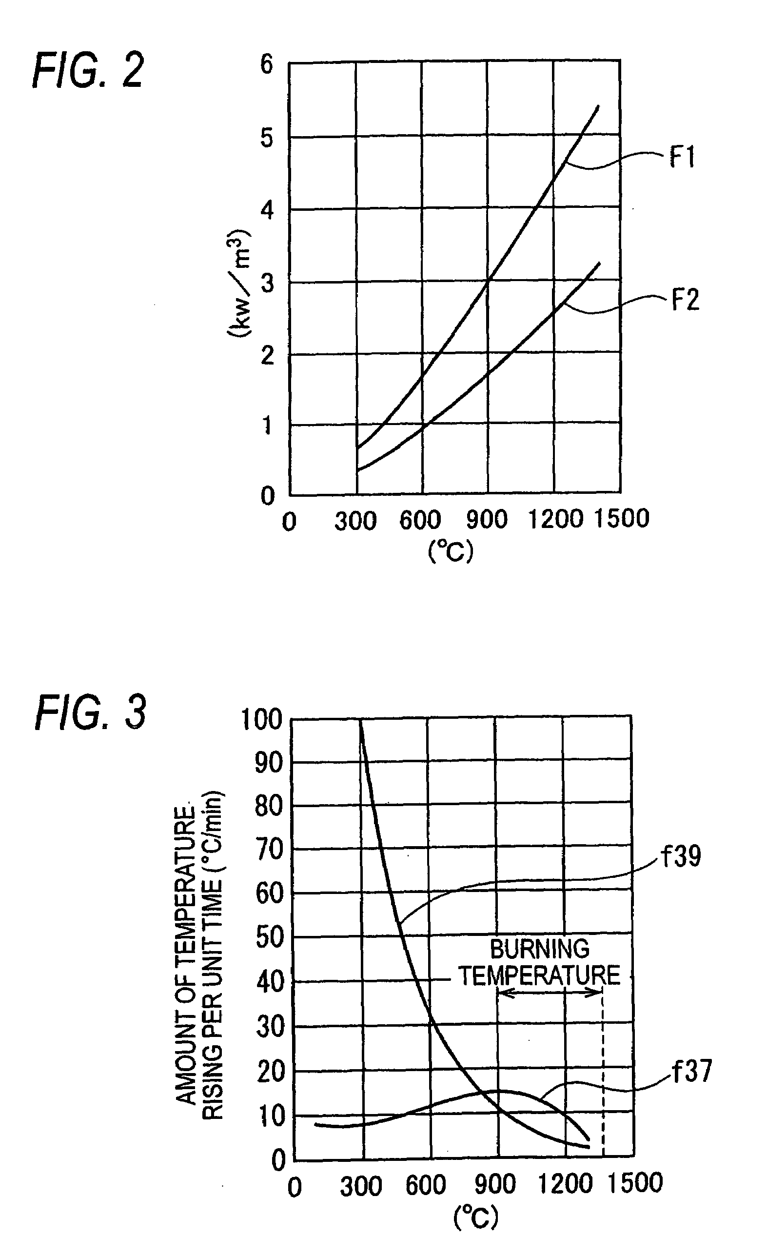
[0043]According to the microwave burning furnace in accordance with the invention, the heating material for a low temperature region which is the formation material of the plural-heater element generates a heat at a high energy efficiency, thereby quickening a rise in an ambient temperature in the temperature rising in the low temperature region at an early stage of the heating carried out by the microwave heating. When the microwave heating is progressed so that the temperature of the heater element is raised to a predetermined high temperature region, the heating material for a high temperature region generates a heat at an original high energy efficiency, thereby raising the ambient temperature.
[0044]In other words, each of the temperature rising in the low temperature region and the temperature rising in the high temperature region can be efficiently implemented by only the microwave heating. In particular, there has been a problem in that the material of the object to be burned uses, as a raw material, alumina or silica to be the main material of ceramics having a small dielectric loss at an ordinary temperature, and the conventional apparatus has a poor energy efficiency by the microwave heating in the temperature rising in the low temperature region in the burning. On the other hand, only the microwave can fulfill the function of a heater even if the heater is not provided in the microwave burning furnace. Thus, the burning can be progressed smoothly at a high energy efficiency.
[0045]In the microwave burning furnace using the heater element constituted by at least two types of materials including the heating material for a low temperature region taking a larger amount of heat generation than the amount of heat generation of the heating material for a high temperature region from the low temperature region including the ordinary temperature to the region which is less than the high temperature region to have the burning temperature and the heating material for a high temperature region taking the amount of heat generation which is equal to or larger than that of the heating material for a low temperature region in the high temperature region to have the burning temperature, moreover, it is possible to control the temperature rising speed in the low temperature region and the temperature rising speed in the high temperature region during the microwave heating. Consequently, it is possible to suppress the generation of a difference in a temperature between the object to be burned and the ambient atmosphere from the low temperature region to the high temperature region and to implement the heating and burning with high precision which prevents the generation of a crack.
[0046]In the case in which the heater element having the main part formed by the heating material for a high temperature region and the heating material for a low temperature region incorporated partially is used, moreover, it is possible to carry out the burning by various manufacturing methods of forming a housing for embedding the heating material for a low temperature region at a proper interval in an inner-shell base metal formed previously by the heating material for a high temperature region and then incorporating the heating material for a low temperature region formed to take the shape of the housing. The inner shell thus formed can be handled as a single component. Therefore, an excellent handling property can be obtained in the assembly of the burning furnace.
[0047]In the burning chamber having a plural-heater element constituted by at least two types of heating materials including the heating material for a high temperature region and the heating material for a low temperature region and a single-heater element constituted by a single heating material of the heating material for a low temperature region or the heating material for a high temperature region, moreover, a proper heater element is provided by the electric field of a microwave in the burning chamber. Thus, it is possible to prevent the intensive heating of the microwave.
[0048]In the burning furnace in which the burning chamber has a plural-heater element constituted by at least two types of heating materials including the heating material for a high temperature region and the heating material for a low temperature region and includes at least two heater elements having different quantities of the heating material for a low temperature region in the plural-heater element, there is provided the plural-heater element including the heating material for a low temperature region having different quantities depending on the electric field of the microwave in the burning chamber. Consequently, it is possible to prevent the intensive heating of the microwave and to produce such an advantage as to relieve the distribution of the electric field of the microwave by the plural-heater element, thereby enhancing the utilization efficiency of the microwave.

Problems solved by technology

As a result, a temperature gradient is generated between a central part and a surface in the object to be burned so that a crack is apt to be generated.
In the burning to be carried out by the microwave heating, moreover, there is also a problem in that an energy effect is obtained poorly by the microwave heating through temperature rising in a low temperature region in the case in which the material of the object to be burned uses, as a raw material, alumina or silica which is the main material of ceramics having a small dielectric loss at an ordinary temperature.
For this reason, there is a problem in that the amount of an energy required for the burning is increased considerably.
In the technique in each of the Documents, however, there is a problem in that the structure of the microwave burning furnace is complicated and a cost is thus increased.
Furthermore, there is also a problem in that power supplies having large capacities are to be mounted for supplying a power for a microwave generator and a heater respectively.
These problems cause a drawback that the structure is complicated and the cost is increased.
In case of JP-A-2002-130960, moreover, some advantages can be obtained for suppressing the generation of the temperature gradient and there is also a problem in that an effect for an improvement in an energy efficiency in the temperature rising in the low temperature region is poor.

Method used


Image

  • Microwave burning furnace including heating element having two types of materials
  • Microwave burning furnace including heating element having two types of materials
  • Microwave burning furnace including heating element having two types of materials

Examples


first embodiment

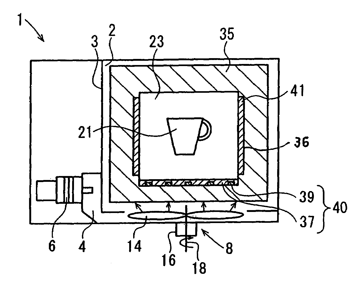
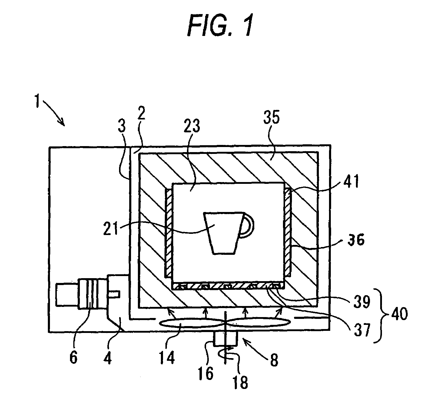
[0064]FIG. 1 shows the microwave burning furnace according to the invention. A microwave burning furnace 1 according to the embodiment serves to burn the material of a pottery and fine ceramics by microwave heating and comprises a cavity 3 for dividing a microwave space 2, a magnetron 6 to be microwave generating means which is connected to the cavity 3 through a waveguide 4 and serves to irradiate a microwave into the cavity 3, microwave stirring means 8 for stirring the microwave irradiated into the cavity 3, a partition wall 35 formed by a heat insulator which is provided in the cavity 3 and serves to transmit a microwave, and a heater element 36 provided on the internal wall of the partition wall 35 and serving to generate a heat through the microwave.

[0065]The cavity 3 has such a structure that at least an internal surface reflects a microwave into the microwave space 2 to prevent the leakage of the microwave.

[0066]The microwave stirring means 8 includes a stirring blade 14 pro...

seventh embodiment

[0097]FIG. 10 shows the microwave burning furnace according to the invention.

[0098]A microwave burning furnace 31 according to the embodiment serves to burn the material of a pottery and fine ceramics by microwave heating and comprises a cavity 3 for dividing a microwave space 2, a magnetron 6 to be microwave generating means which is connected to the cavity 3 through a waveguide 4 and serves to irradiate a microwave into the cavity 3, microwave stirring means 8 for stirring the microwave irradiated into the cavity 3, and a blanket 42 provided in the cavity 3 and surrounding an object 21 to be burned.

[0099]The cavity 3 has such a structure that at least an internal surface reflects a microwave into the microwave space 2 to prevent the leakage of the microwave.

[0100]The microwave stirring means 8 includes a stirring blade 14 provided in the cavity 3, a driving motor 16 provided on the outside of the cavity 3, and a rotation transmitting shaft 18 for transmitting the rotation of the d...


PUM

PropertyMeasurementUnit
microwave absorptionaaaaaaaaaa
heat insulating propertyaaaaaaaaaa
temperatureaaaaaaaaaa

Abstract

A microwave burning furnace including a housing constituted by a metal on which a microwave is to be irradiated, a metallic door provided in the housing, a burning chamber provided in the housing and surrounded by a material having a low microwave absorption characteristic and a high heat insulating property, and microwave generating means, wherein the burning chamber includes a heater element constituted by at least two types of heating materials having a heating material for a high temperature region which automatically generates a heat mainly in the high temperature region to have a burning temperature by an irradiation of a microwave and a heating material for a low temperature region which automatically generates a heat mainly in the low temperature region including an ordinary temperature.

Description

BACKGROUND OF THE INVENTION[0001]The present invention relates to a microwave burning furnace for burning an object to be burned which is formed by the material of a pottery or fine ceramics material, thereby manufacturing a burned product.[0002]In recent years, it has been proposed to burn the material of a pottery or fine ceramics by microwave heating, and practical use has already been started.[0003]In the case in which they are to be burned by the microwave heating, a microwave uniformly heats each portion of an object to be burned in principle if the object to be burned is homogeneous. In a burning process, however, an atmospheric temperature in a microwave burning furnace is much lower than the surface temperature of the object to be burned. For this reason, a heat is radiated from the surface of the object to be burned. As a result, a temperature gradient is generated between a central part and a surface in the object to be burned so that a crack is apt to be generated.[0004]...

Claims


Application Information

Patent Timeline
Patent Type & Authority Patents(United States)
IPC IPC(8): H05B6/80C04B35/64F27D11/12H05B6/64
CPCH05B6/6494
Inventor NOMURA, EIJINOMURA, JUNSATO, MOTOYASU
Owner PANASONIC CORP
Learn More