Radiological imaging apparatus and its detector unit

a detector unit and imaging apparatus technology, applied in the direction of instruments, x/gamma/cosmic radiation measurement, radiation control devices, etc., can solve the problems of insufficient structure studies and difficulty in maintaining, and achieve the effect of reducing noise components, suppressing noise superimposition, and facilitating space shielding

Inactive Publication Date: 2007-05-15
HITACHI LTD
View PDF17 Cites 12 Cited by
  • Summary
  • Abstract
  • Description
  • Claims
  • Application Information

AI Technical Summary

Benefits of technology

[0008]Since the areas of the plurality of detector units housed in the housing supported by the support member in which the semiconductor radiation detectors exist protrude from the opening of the housing and disposed inside the support member, no housing exists between the neighboring detector units in the circumferential direction of the support member. Thus, it is possible to bring the semiconductor radiation detectors of the neighboring detection units inside the support member closer to each other and improve an arrangement density of semiconductor radiation detectors in the circumferential direction of the support member. This improves the detection spatial resolution of γ-rays and improves positional resolution of a tomogram of an examinee. Providing a tomogram with high positional resolution makes it possible to detect smaller cancers and conduct a detailed diagnosis. It also allows detector units to be replaced unit by unit and facilitates replacement of the radiation detectors.
[0022]The present invention facilitates replacement of the radiation detectors and can improve an arrangement density of radiation detectors. This allows, for example, the radiological imaging apparatus to obtain a clear image of the examinee.

Problems solved by technology

On the other hand, when many detectors are used, maintenance thereof may become difficult.
However, conventionally there have not been enough studies on a structure which would satisfy both a structure of equipment for obtaining an image with high resolution and a structure of equipment for making maintenance easier.

Method used


Image

  • Radiological imaging apparatus and its detector unit
  • Radiological imaging apparatus and its detector unit
  • Radiological imaging apparatus and its detector unit

Examples


first embodiment

(First Embodiment)

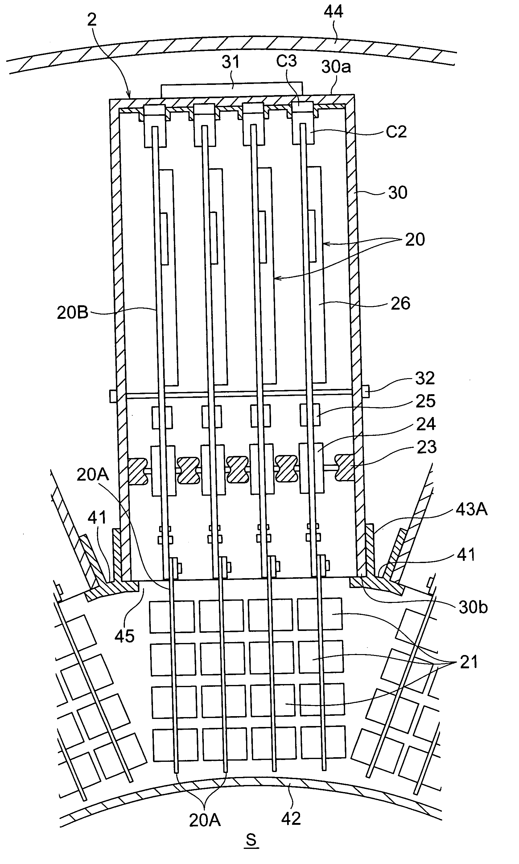
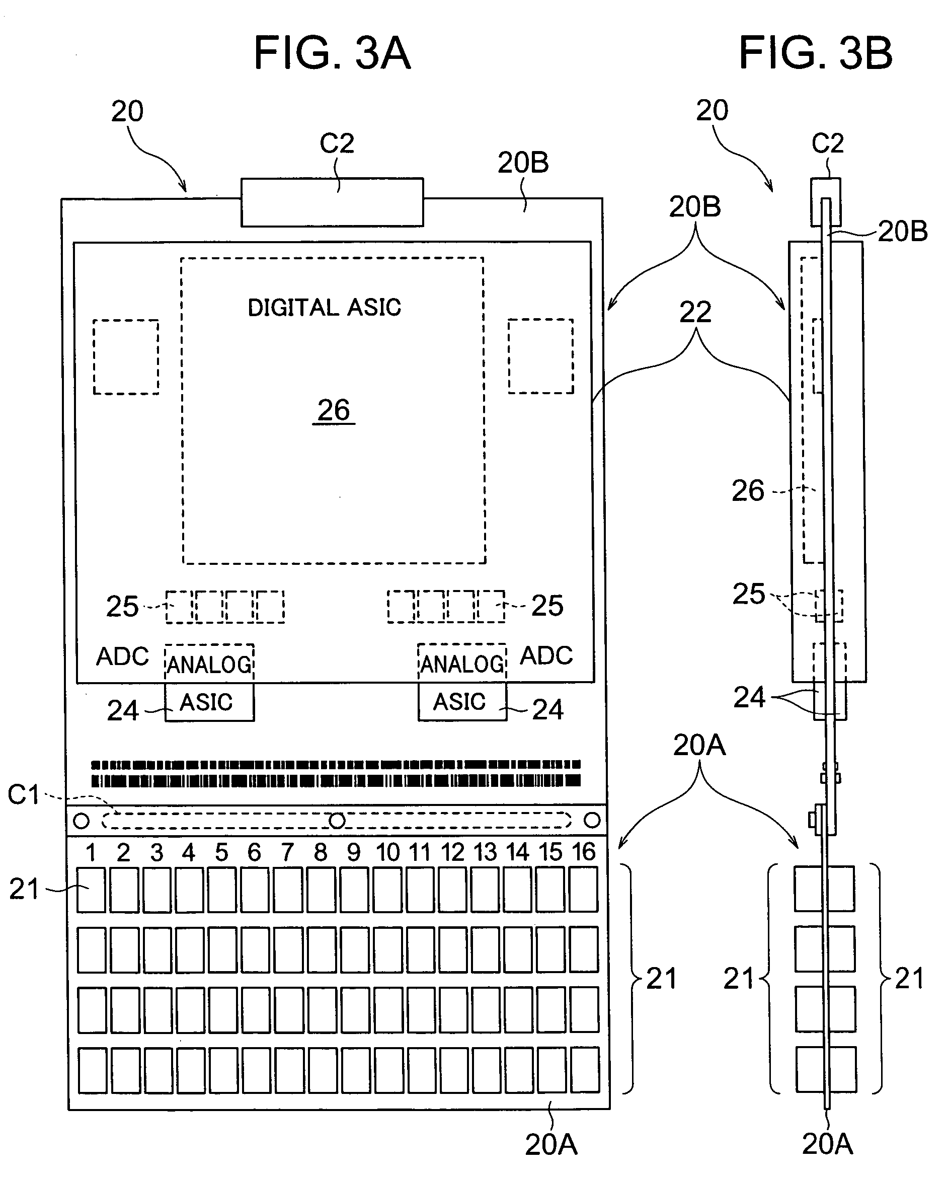
[0038]With reference to FIGS. 1 to 7, a first embodiment of the present invention will be explained.

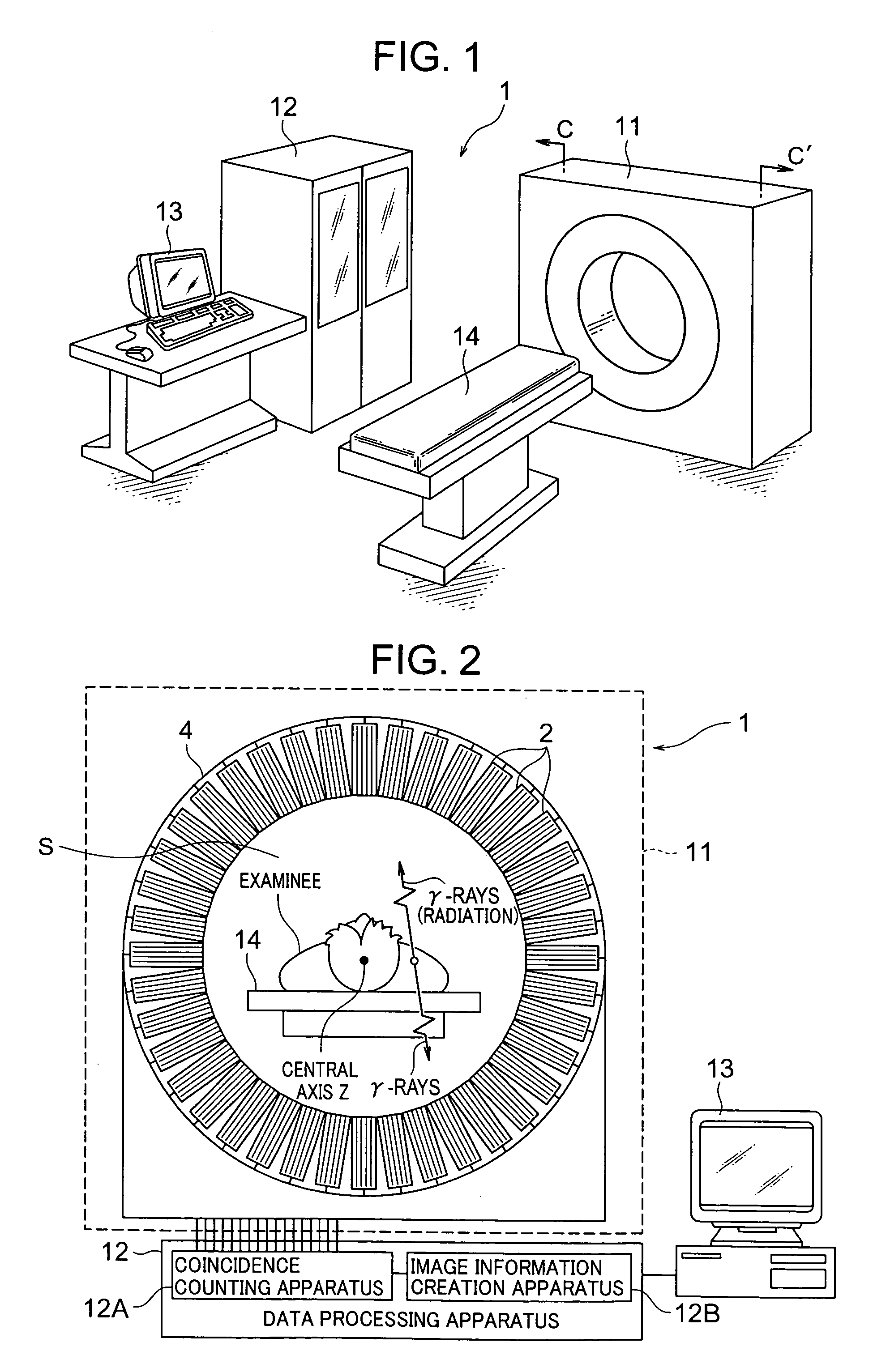
[0039]As shown in FIG. 1, a PET apparatus 1 (radiological imaging apparatus) is constructed by including an imaging apparatus 11, a data processing apparatus 12 which processes detection data obtained by this imaging apparatus 11 and converts the detection data to image data, a display device 13 which displays the image data (PET image information) output from this data processing apparatus 12 two-dimensionally or three-dimensionally and an examining table 14 on which an examinee is laid.

[0040]The examinee is given radiopharmaceutical, for example, fluorodeoxyglucose (FDG) containing 18F having a half life of 110 minutes and pairs of γ-rays (radiation) generated when FDG positrons are annihilated are emitted from within the body of the examinee in directions of 180°±0.6° simultaneously. The radiopharmaceutical used in an inspection using the PET apparatus 1 emits pos...


PUM


Abstract

A radiological imaging apparatus capable of improving an arrangement density of semiconductor radiation detectors and detector units thereof, each detector unit consisting of a plurality of combined substrates having a detector substrate which includes semiconductor radiation detectors and a signal processing substrate which includes integrated circuits, housed in a housing. The detector substrate protrudes outward from an opening of the housing. A plurality of detector units are attached to a ring-shaped unit support section in a circumferential direction thereof. More specifically, the detector substrate protrudes inward from the unit support section and the housing is attached to the unit support section.

Description

BACKGROUND OF THE INVENTION[0001]The present invention relates to a radiological imaging apparatus and detector unit thereof.[0002]A radiological imaging apparatus such as a positron emission tomography (hereinafter referred to as “PET apparatus”) for diagnosing an examinee by detecting radiation emitted from the examinee given radioisotope and laid on an examining table using detectors arranged around the examinee is known.[0003]The PET apparatus is an apparatus which administers radioisotope to an examinee, detects γ-rays emitted from within the body of this examinee using γ-ray detectors arranged around the examinee and outputs a two-dimensional or three-dimensional image of the examinee (e.g., see JP-A-2003-185750 (paragraph 0002, FIG. 12)).[0004]In a nuclear medicine diagnosis using such a radiological imaging apparatus, a diagnosis is conducted by obtaining a two-dimensional or three-dimensional image of the examinee. For this purpose, it is important to obtain a two-dimension...

Claims


Application Information

Patent Timeline
Patent Type & Authority Patents(United States)
IPC IPC(8): G01T1/24G01T1/161G01T1/29
CPCG01T1/2928
Inventor UENO, YUUICHIROUKOJIMA, SHINICHIYANAGITA, NORIHITOAMEMIYA, KENSUKEKITAGUCHI, HIROSHITSUCHIYA, KATSUTOSHIYOKOI, KAZUMAISHITSU, TAKAFUMI
Owner HITACHI LTD
Why Eureka
Try Eureka