Optical fiber, optical fiber device, and optical fiber bundle
a technology of optical fiber and optical fiber bundle, which is applied in the field of optical fiber, optical fiber devices, optical fiber bundles, etc., can solve the problem that cannot become a perfect therapeutic method
- Summary
- Abstract
- Description
- Claims
- Application Information
AI Technical Summary
Benefits of technology
Problems solved by technology
Method used
Image


Examples
first embodiment
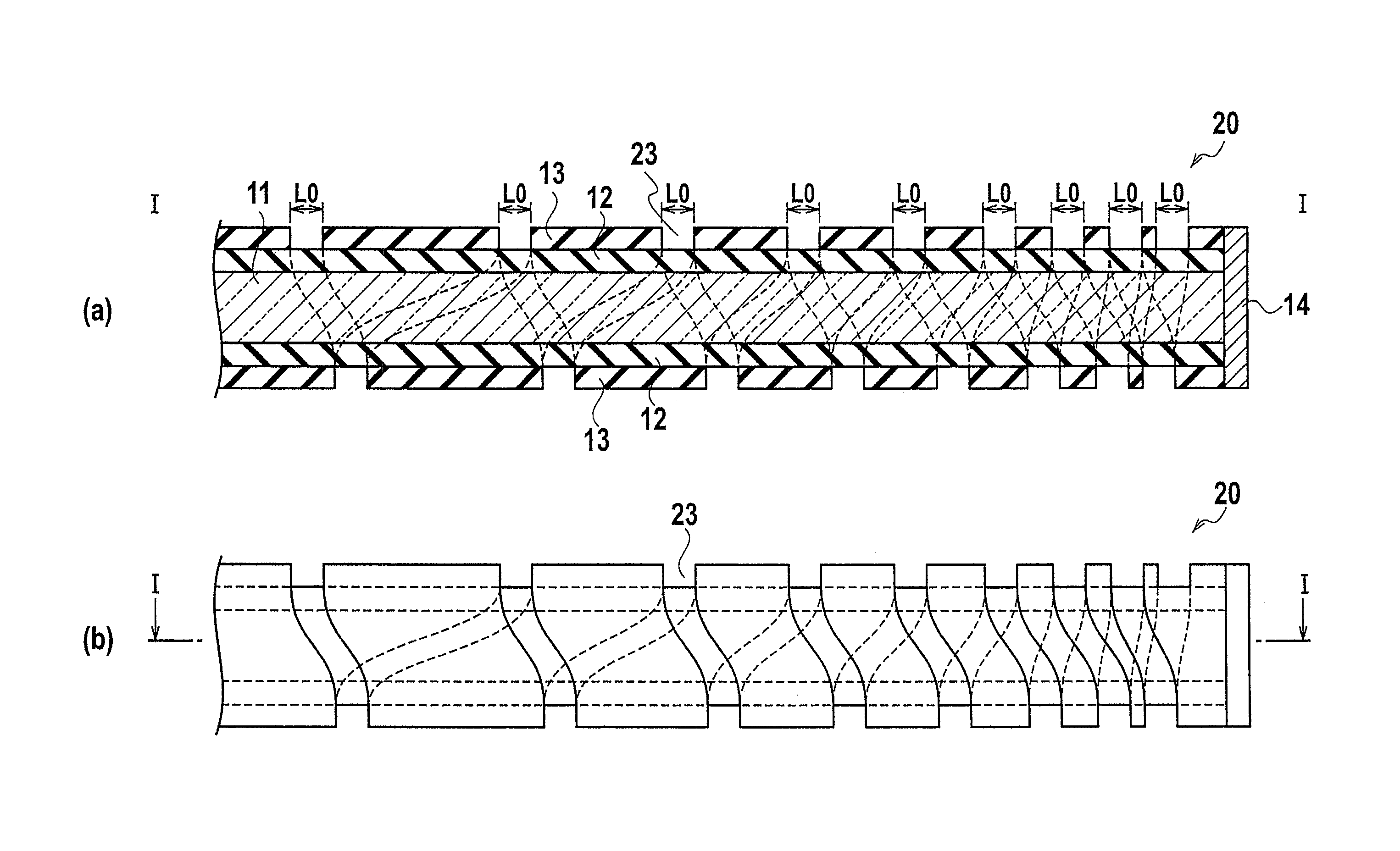
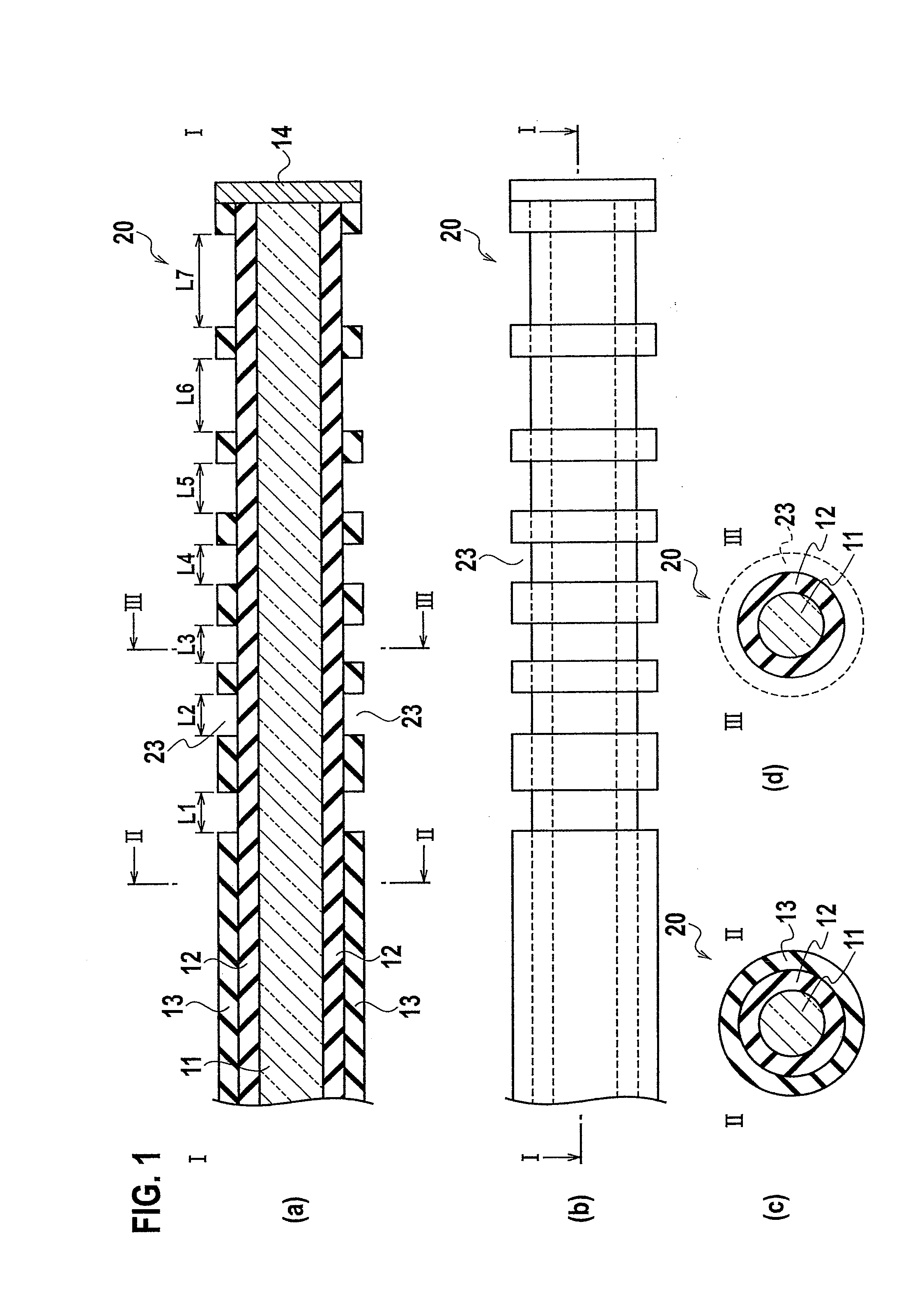
[0072]An optical fiber 20 according to the first embodiment of the present invention is expressed as shown in FIG. 1. FIG. 1(a) is a schematic cross-sectional configuration diagram taken in the line I-I of FIG. 1(b), FIG. 1(b) is a schematic plan view of the optical fiber 20, FIG. 1(c) is a schematic cross-sectional configuration diagram taken in the line II-II of FIG. 1(a), and FIG. 1(d) shows a schematic cross-sectional configuration diagram taken in the line III-III of FIG. 1(a).
[0073]As shown in FIG. 1, the optical fiber 20 according to the first embodiment of the present invention is an optical fiber which can be inserted in a tubular tissue in an organism, and includes: a glass core layer 11; a covering core layer 12 which covers the glass core layer 11; and a cladding layer 13 which covers the covering core layer 12 and includes a plurality of apertural areas 23 in the longitudinal direction of the optical fiber 20. In the longitudinal direction of the optical fiber 20, the w...
second embodiment
[0097]An optical fiber 20 according to a second embodiment of the present invention is expressed as shown in FIG. 2. FIG. 2(a) is a schematic cross-sectional configuration diagram taken in the line I-I of FIG. 2(b), FIG. 2(b) is a schematic plan view of the optical fiber 20, FIG. 2(c) is a schematic cross-sectional configuration diagram taken in the line II-II of FIG. 2(a), and FIG. 2(d) shows a schematic cross-sectional configuration diagram taken in the line III-III of FIG. 2(a).
[0098]As shown in FIG. 2, the optical fiber 20 according to the second embodiment of the present invention is an optical fiber which can be inserted in a tubular tissue in an organism, and includes: a glass core layer 11; a covering core layer 12 which covers the glass core layer 11; and a cladding layer 13 which covers the covering core layer 12 and includes a plurality of apertural areas 23 having the given width L0 in the longitudinal direction of the optical fiber 20. The arrangement density of the ape...
third embodiment
[0109]An optical fiber 20 according to a third embodiment of the present invention is expressed as shown in FIG. 3. FIG. 3(a) is a schematic cross-sectional configuration diagram taken in the line I-I of FIG. 3(b), FIG. 3(b) is a schematic plan view of the optical fiber 20, FIG. 3(c) is a schematic cross-sectional configuration diagram taken in the line II-II of FIG. 3(a), and FIG. 3(d) shows a schematic cross-sectional configuration diagram taken in the line III-III of FIG. 3(a).
[0110]As shown in FIG. 3, the optical fiber 20 according to the third embodiment of the present invention is an optical fiber which can be inserted in the tubular tissue in the organism, and includes: a glass core layer 11; a covering core layer 12 which covers the glass core layer 11; and a cladding layer 13 which covers the covering core layer 12 and includes a plurality of apertural areas 23 having constant width in the longitudinal direction of the optical fiber 20. The arrangement density of the apertu...
PUM
 Abstract
Description
Claims
Application Information
 - R&D
- Intellectual Property
- Life Sciences
- Materials
- Tech Scout
- Unparalleled Data Quality
- Higher Quality Content
- 60% Fewer Hallucinations
Browse by: Latest US Patents, China's latest patents, Technical Efficacy Thesaurus, Application Domain, Technology Topic, Popular Technical Reports.
© 2025 PatSnap. All rights reserved.Legal|Privacy policy|Modern Slavery Act Transparency Statement|Sitemap|About US| Contact US: help@patsnap.com