
Image printing method and apparatus

a printing method and image technology, applied in the field of image printing methods and apparatuses, can solve the problems of affecting the speed of affecting the accuracy of the image correction, and the inability to speed up the read timing correction processing of the dmax sensor, so as to accurately correct the read timing of the sensor system and the magnification of the imag

Inactive Publication Date: 2007-05-01
KONICA MINOLTA INC
View PDF7 Cites 2 Cited by
  • Summary
  • Abstract
  • Description
  • Claims
  • Application Information

AI Technical Summary

Benefits of technology

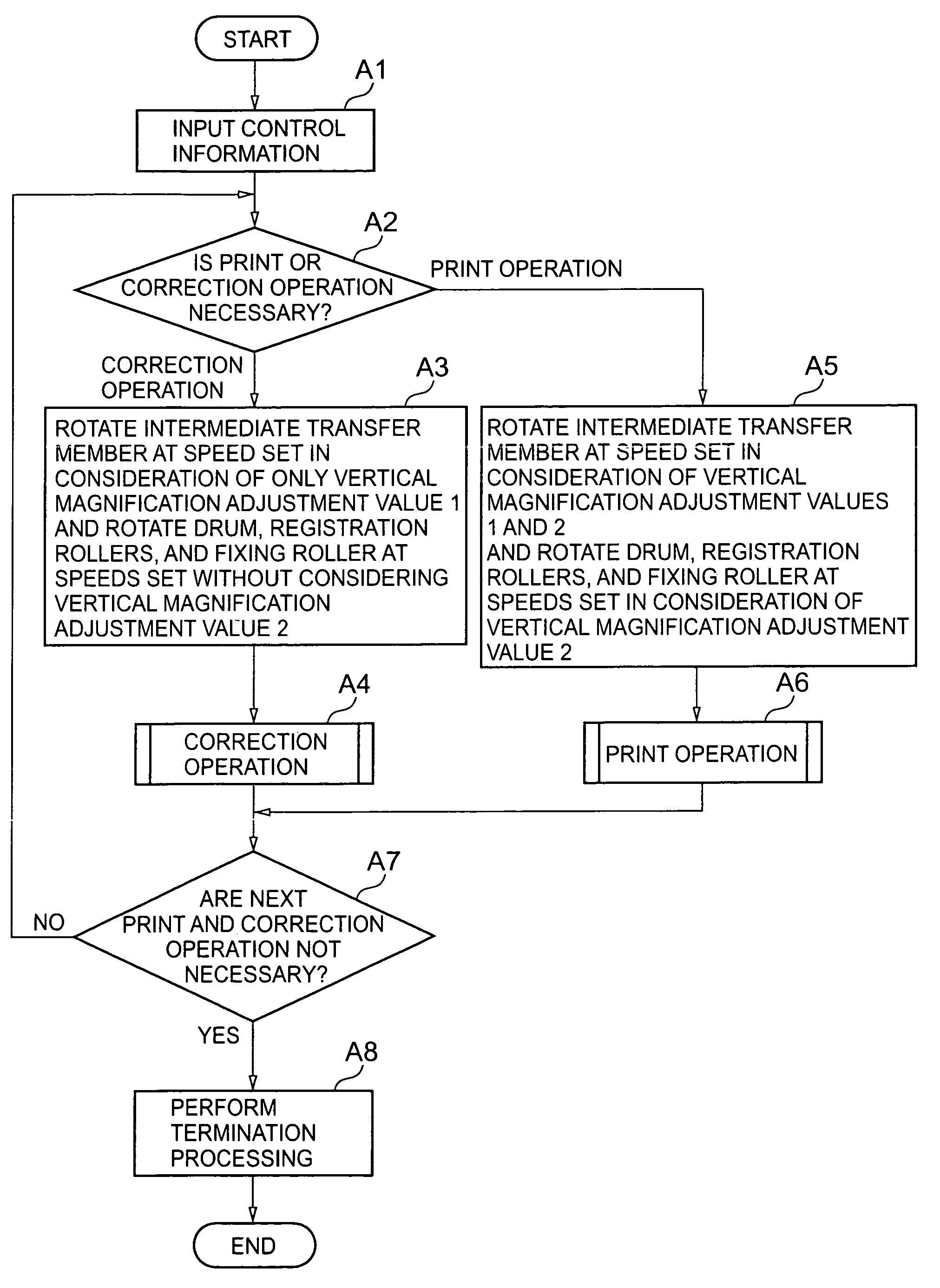
[0022]The present invention has been made to solve the above inconveniences in the prior art, and has as its object to provide an image printing method and apparatus which can accurately correct the read timing of a sensor system which is used to correct the position of a toner image in the correction operation mode, and can accurately correct the magnification of an image in the vertical direction in the print operation mode.
[0033]In the first mode, the image printing member can be rotated on the basis of only the first vertical magnification adjustment value independent of a value for adjusting the vertical magnification of an image printed on a paper sheet as in the second mode. This makes it possible to accurately correct the read timing of the sensor system including the first and second detection units and the like, which are used to correct the position of a toner image, so as to eliminate the mechanical assembly tolerance or the like of the image printing unit.
[0034]In addition, since a patch image to be printed to read the density of a toner image can be printed small, the correction time can be shortened, and the consumption of toner in correction operation can be reduced.
[0035]In the second mode, the image printing member can be rotated on the basis of the second vertical magnification adjustment value in addition to the rotational speed conditions provided for the sensor system or image printing member having undergone accurate timing correction in the first mode. This makes it possible to accurately adjust the magnification of an image in the vertical direction so as to correct image reduction which sometimes occurs depending on the type or size of paper sheet. Therefore, the image on a paper sheet which is obtained from the image printing unit can be matched with a target image print size, thereby printing a high-quality image.
[0036]According to the image printing method of the present invention, when an image is to be printed on a desired paper sheet, the image printing member can be rotated in the first mode on the basis of only the first vertical magnification adjustment value independent of a value for adjusting the vertical magnification of an image printed on a paper sheet as in the second mode. This makes it possible to accurately correct the read timing of the sensor system including the first and second detection units and the like which are used to correct the position of a toner image.
[0037]In the second mode, the image printing member can be rotated on the basis of the second vertical magnification adjustment value in addition to the sensor system whose timing is accurately corrected in the first mode and the rotational speed conditions for the image printing member. This makes it possible to accurately adjust the magnification of an image in the vertical direction so as to correct image reduction which may occur depending on the type or size of paper sheet.

Problems solved by technology

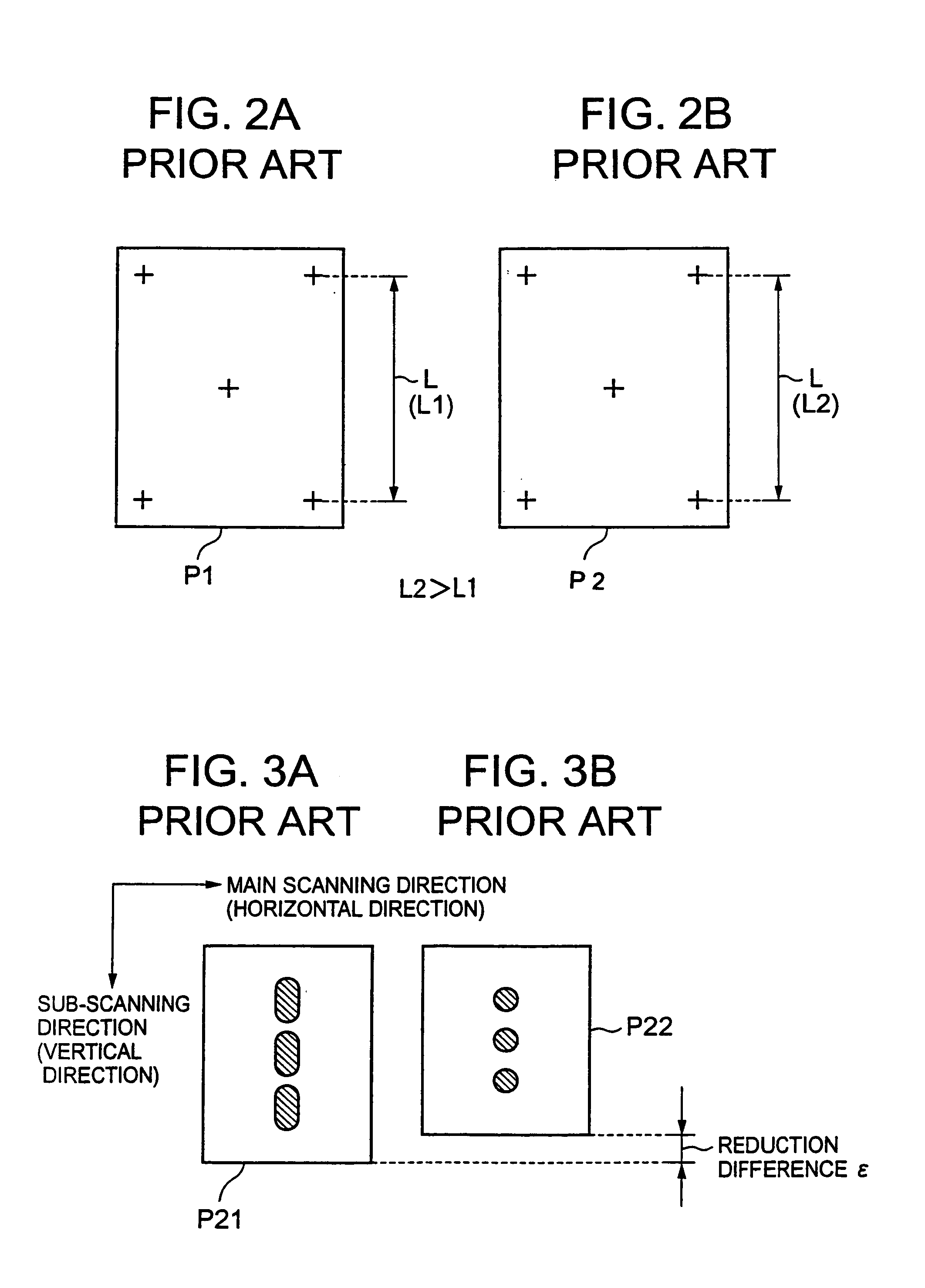
Consequently, a correction image such as a patch image becomes undesirably large in the correction operation mode, and the consumption of toner becomes always larger to the extent that the correction image becomes larger.
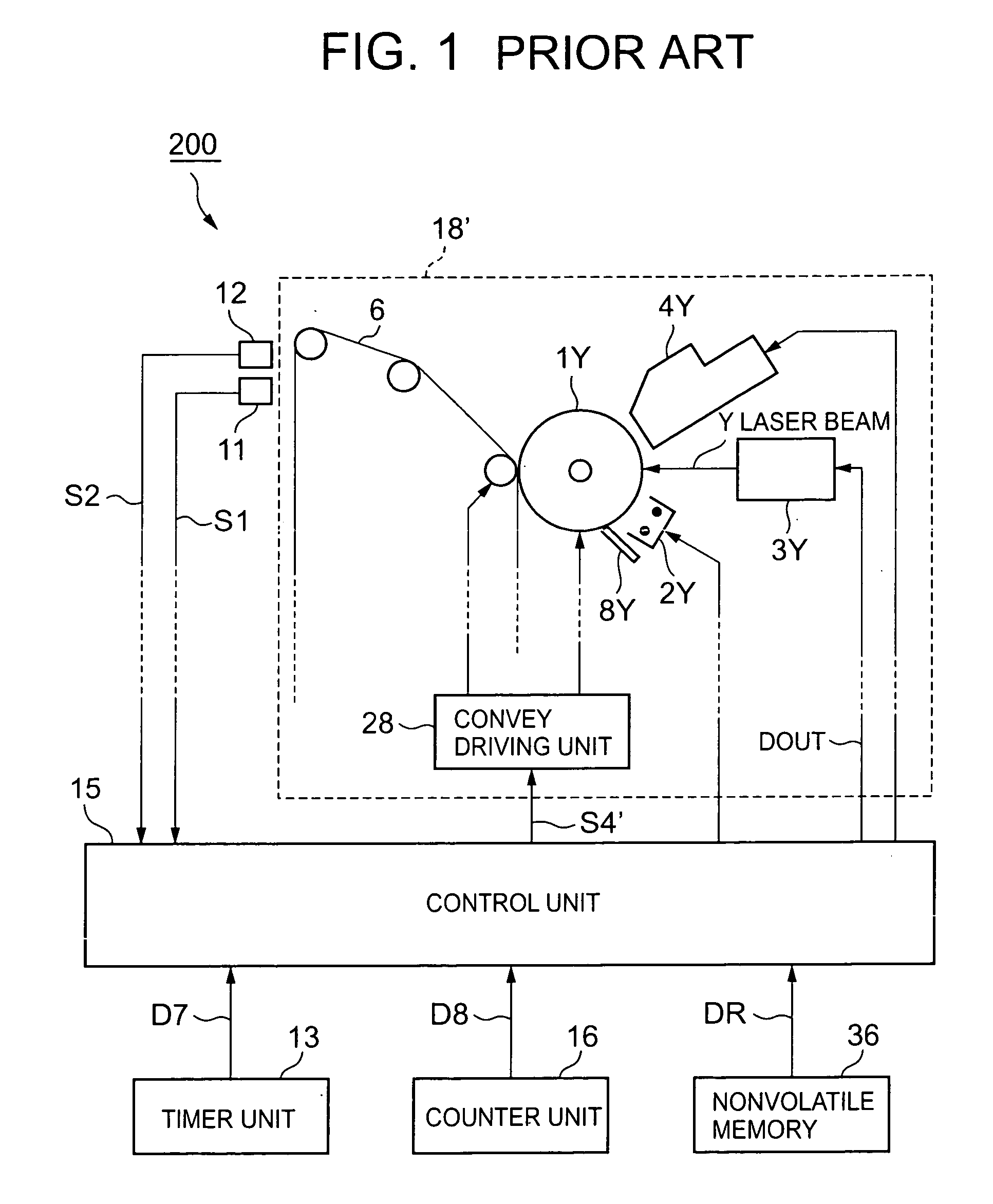
This may hinder attempts to speed up the read timing correction processing of the Dmax sensor 12.
This therefore may cause a deterioration in the correction precision of the read timing of the sensor system or hinder attempts to increase the precision in correcting the magnification of an image in the vertical direction.

Method used


Image

  • Image printing method and apparatus
  • Image printing method and apparatus
  • Image printing method and apparatus

Examples


Embodiment Construction

[0050]An image printing method and apparatus according to a preferred embodiment of the present invention will be described below with reference to the accompanying drawings.

[0051]FIG. 5 is a conceptual view showing the schematic arrangement of a color digital copying machine 100 to which an image printing apparatus as an embodiment of the present invention is applied.

[0052]This embodiment includes a control unit which controls the rotational speed of an image printing member upon detecting a toner image printed on the image printing member when an image is to be printed on a desired paper sheet. When the first mode (to be referred to as a correction operation mode hereinafter) for the image printing member is selected, the control unit executes feedback control on the rotational speed of the image printing member on the basis of the first vertical magnification adjustment value. When the second mode (to be referred to as a print operation mode hereinafter) is selected, the control ...


PUM


Abstract

This invention provides an image printing method and apparatus which accurately correct the read timing of a sensor system used to correct the position of a toner image in the correction operation mode, and accurately corrects the magnification of an image in the vertical direction in the print operation mode. An image printing apparatus according to the invention includes an image printing unit which prints a toner image on an intermediate transfer belt, and a control unit which controls the rotational speed of the intermediate transfer belt by detecting a toner image printing on the intermediate transfer belt by the image printing unit. When the correction operation mode is selected, the control unit executes feedback control on the rotational speed of the intermediate transfer belt on the basis of vertical magnification adjustment value data. When the print operation mode is selected, the control unit executes feedback control on the rotational speed of the intermediate transfer belt on the basis of vertical magnification adjustment value.

Description

BACKGROUND OF THE INVENTION[0001]1. Field of the Invention[0002]The present invention relates to an image printing method and apparatus which can be suitably applied to a color digital copying machine, multifunction apparatus, and the like which print a color image based on color image information and output it.[0003]2. Description of the Prior Art[0004]Recently, a color image printing apparatus has been put into practice, which is designed to print a color image on the basis of red (R), green (G), and blue (B) image data acquired from a colored original image or receive image data from a printer controller (external apparatus) such as a server or personal computer (to be simply referred to as a PC hereinafter) to print a color image on the basis of the image data. A color image printing apparatus of this type is disclosed in Japanese Unexamined Patent Publication No. 2002-72771 (see pp. 14–25 and FIG. 5 of this reference).[0005]FIG. 1 is a block diagram showing the schematic arrang...

Claims


Application Information

Patent Timeline
IPC IPC(8): G03G15/16G03G21/00G03G15/00G03G15/01G03G21/14H04N1/29
CPCG03G15/0131G03G2215/0119G03G2215/0158
Inventor KUDOU, TOMOOAKIMOTO, FUSAKOARAI, HIROYUKI
Owner KONICA MINOLTA INC
Learn More