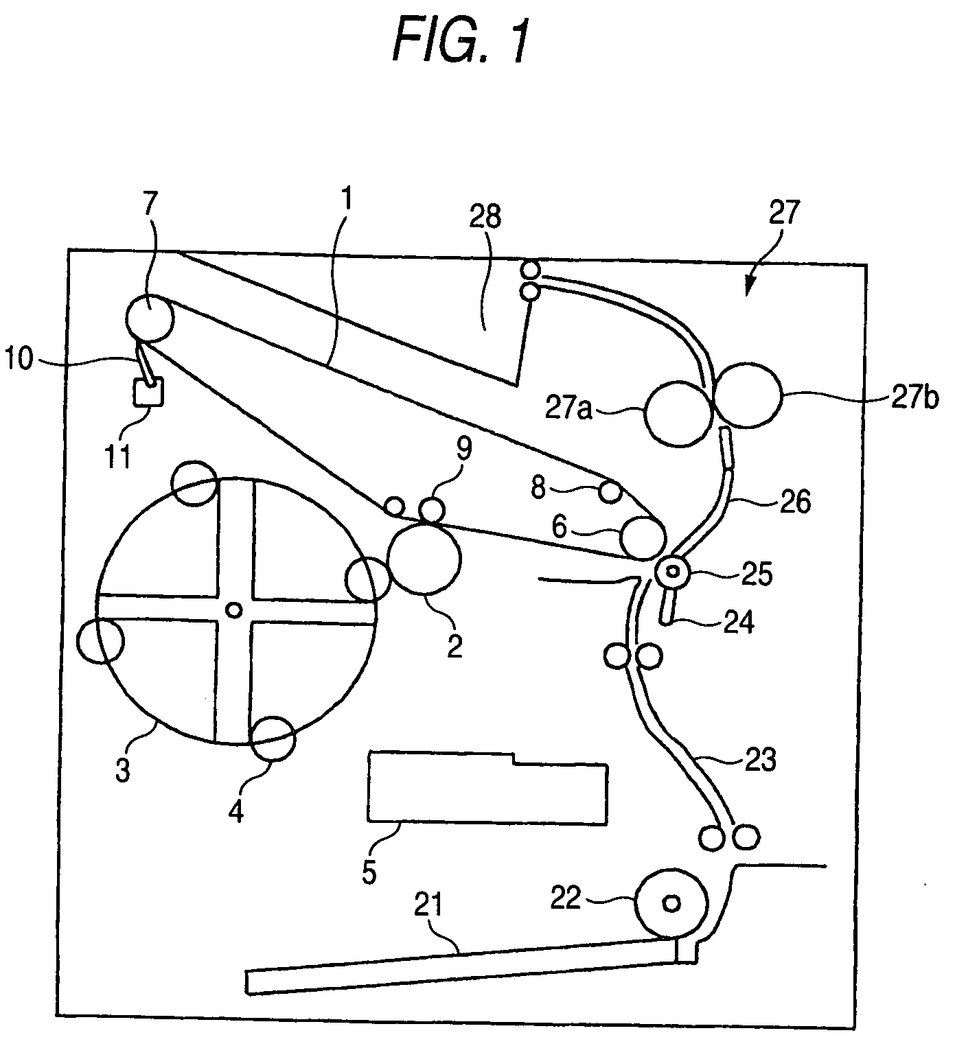
Image forming apparatus having a medium transporting belt formed in an endless shape and having a first and second region

a technology of transporting belt and image carrier, which is applied in the direction of electrographic process apparatus, instruments, optics, etc., can solve the problems of oblique seam extending direction that does not consider, transfer failure, and welding becomes unstable according to the direction

Inactive Publication Date: 2007-04-24
SEIKO EPSON CORP
View PDF21 Cites 4 Cited by
  • Summary
  • Abstract
  • Description
  • Claims
  • Application Information

AI Technical Summary

Benefits of technology

[0007]On the other hand, Japanese Patent Publication No. 9-146386A discloses a similar endless intermediate transfer belt, in order to prevent the seam from bounding when it passes a cleaning blade to enhance the cleaning ability. Further this publication teaches that a reinforcement for the seam is adhered on the belt so as to extend obliquely relative to the circulating direction of the belt, in order to suppress the circulating speed fluctuation due to the seam.
[0049]It is also an object of the invention to provide an image forming apparatus capable of alleviating impact generated when a cleaning member or a secondary transfer member is brought into contact with an intermediate transfer member.

Problems solved by technology

However, these publications does not consider the extending direction of the oblique seam.
Therefore, in a case where the oblique seam is extended such that an end of the seam confronting the electrode layer is situated in the downstream side, the toner conveyed along the seam contaminate the electrode layer so that the transfer failure would be occurred.
In a case where the belt is seamed by ultrasonic welding, the welding becomes unstable according to the above thickness difference.
Therefore, the upstream side of the seam is liable to break firstly.
Since the belt continues to be used under such a condition, the broken portion would damage the cleaning blade, the photoconductive member or the like.
Further, in a case where the bias voltage is applied to the electrode layer through a roller member, a plate spring or the like, the broken portion is likely to be caught by such members, so that the breakage would progress in an instant.
Although there is a case where a mark is printed on the belt so as to have a different color from the color of the belt, erroneous operation would be caused when the mark is dirtied with toner or dust.
Although the tension applied to the belt may be released mechanically, it is necessary to provide an additional mechanism to perform the release operation, thereby disabling the downsizing of the apparatus.
Further, since it is necessary to again apply the tension from the released condition when the printing operation is activated, there poses a problem that a time is taken from instructing to print to starting to print.
Although it is unavoidable that creep is produced at the belt at a portion thereof made to wrap on the roller, when the belt is stopped, there is a case where the position detecting hole or the position detecting projection of the belt is brought into a state of being made to wrap on the roller.
In that case, when the belt is moved again, in the case of the reflective sensor, the position detecting hole is deformed and therefore, gain of reflection is reduced and accuracy of detecting the position is deteriorated.
Further, the sensor is liable to be brought into contact with uneven portions produced by the deformation to wear the detection mark to pose a problem that the position is detected inaccurately.
Further, in the case of the transmissive sensor, there is a case where uneven portions produced at the position detecting portion are liable to be caught by the small interval between the light emitter and the light receiver to break the belt.
In such an image forming apparatus, when the cleaning blade or the secondary transfer roller is brought into contact with the intermediate transfer belt, impact or vibration effects influence on forming an image, as a result, a failure in image formation such as banding is brought about.
Further, toner is scattered to float by the impact, conduction failure would be brought about when the floated toner is adhered to a conductive member in the apparatus.
Such operation generates a relatively large impact to scatter the toner.
Further, in a case where the seam is obliquely extended relative to the circulating direction of the belt as disclosed in this publication, and in a case where the cleaning member or the secondary transfer member is so configured as to be brought into contact with the belt while avoiding the seam, it is difficult to downsize the intermediate transfer belt because a non-image forming region is accordingly enlarged.

Method used


Image

  • Image forming apparatus having a medium transporting belt formed in an endless shape and having a first and second region
  • Image forming apparatus having a medium transporting belt formed in an endless shape and having a first and second region
  • Image forming apparatus having a medium transporting belt formed in an endless shape and having a first and second region

Examples


example 1

[0137]As an intermediate transfer belt, a metal layer was vapor-deposited on a substrate of a PET (polyethyleneterephthalate) film having a thickness of 130 μm, and a coating dispersed with a conductive material having medium resistance was coated on the metal layer. A projection was formed at a side edge of the belt as a reference position thereof. The projection was detected by a transmissive optical sensor. An interval between a light emitter and a light receiver was 5 mm. The belt was stretched by a drive roller and a plurality of driven rollers.

[0138]In stopping the belt, the belt was controlled to stop such that the projection was deviated from portions wrapping on the rollers. When the belt was stopped for a long time period under the state, unevenness was produced at portions of the belt crept by the rollers. Since the projection was situated so as to avoid the portions wrapping on the rollers, any deformation was not formed on the projection. Using this belt, no damage was ...

example 2

[0139]As an intermediate transfer belt, a substrate of ETFT (ethylenetetrafluoroethylene copolymer) having a thickness of 150 μm dispersed with carbon was used. A mark was painted on a side end portion of the belt as the reference position. A reflective sensor was disposed at a distance of 3 mm from a surface of the belt. The belt was stretched by a drive roller and a plurality of driven rollers.

[0140]In stopping the belt, the belt was controlled to stop such that the projection was deviated from portions wrapping on the rollers. When the belt was stopped for a long time period under the state, unevenness was produced at portions of the belt crept by the rollers. Since the mark was situated so as to avoid the portions wrapping on the rollers, any deformation was not formed on and around the mark. Using this belt, no damage was occurred on the position sensor, no image offset was occurred on the intermediate transfer belt (falls within a range of 10 μm or less).


PUM


Abstract

A belt member is seamed to form an endless belt which is stretched by a plurality of roller members and circulated in a first direction. The belt member is provided with an electrode portion at a first end portion thereof in a second direction perpendicular to the first direction. A cleaning member is abutted against the belt member. A seam of the belt member extends obliquely relative to the first direction such that an end of the seam confronting the electrode portion is situated in an upstream side of the first direction.

Description

BACKGROUND OF THE INVENTION[0001]This is a divisional of application Ser. No. 10 / 705,236 filed Nov. 12, 2003 now U.S. Pat No. 7,085,523. The entire disclosure of the prior application, application Ser. No. 10 / 705,236 is considered part of the disclosure of the accompanying divisional application and is hereby incorporated by reference.[0002]The present invention relates to an image forming apparatus having an image carrier belt or a medium transporting belt formed in an endless shape.[0003]The present invention also relates to an image forming apparatus capable of controlling a stop position of an image carrier belt provided with a position indicator.[0004]The present invention also relates to an image forming apparatus having a cleaning member or a secondary transferring member which is brought into contact with and separated from an intermediate transferring member.[0005]In an intermediate transfer method of an electrophotography process in which a plurality of color images are la...

Claims


Application Information

Patent Timeline
Patent Type & Authority Patents(United States)
IPC IPC(8): G03G15/01G03G15/16
CPCG03G15/161G03G15/162G03G2215/1623G03G2215/1661
Inventor FUJITA, SHIGEOYAMAZAKI, TOSHIHIKOITO, HIROSHIKAMOSHIDA, SHINICHI
Owner SEIKO EPSON CORP
Why Eureka
Try Eureka