
Ball grid array package with heat sink device

a technology of heat sink and package, which is applied in the direction of electrical apparatus construction details, light and heating apparatus, printed circuit non-printed electric components association, etc., can solve the problems of high heat dissipation, easy damage of thermistors, and easy destruction of microprocessor devices or other components proximal to the microprocessor, so as to improve heat dissipation efficiency. , the effect of increasing the heat dissip

Inactive Publication Date: 2007-04-24
SILICON INTEGRATED SYSTEMS
View PDF19 Cites 47 Cited by
  • Summary
  • Abstract
  • Description
  • Claims
  • Application Information

AI Technical Summary

Benefits of technology

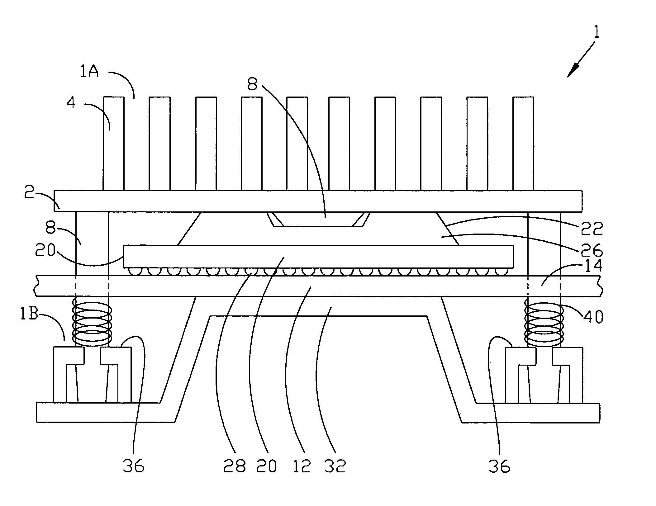
The present invention provides a heat sink device for a ball grid array package device with a modified embedded heat slug to improve heat dissipating efficiency. The heat sink device includes two heat sink assemblies and a thermal block located below the first heat sink assembly. The second heat sink assembly is a bottom plate with a protruding structure and at least two openings for thermal supports. The invention also provides at least two thermal supports to join the openings of the first heat sink assembly and the second heat sink assembly, which fixes the whole package device. The technical effects of this invention are to increase heat dissipating efficiency, improve heat dissipating efficiency, and remove heat from the die or chip.

Problems solved by technology

The PENTIUM microprocessor contain millions of transistors, and they are highly susceptible to overheating.
Therefore, the microprocessor device itself or other components proximal to the microprocessor are easy to be destroyed because of overheating.
At least some of these semiconductor package devices also have the above-mentioned problem.
For example, the resistors and thermistors generate large volumes of heat during normal operation, and if the heat can not be dissipated quickly to cool down the resistors and thermistors they can be destroyed and damaged by the heat.
For example, any electronic package device may have a threat of overheating, and need to be cooled down to prevent overheating.
However, the devices are too small to adequately support and receive the typical metallic heat sink.
Further, gap pads out the interface surface between the package device and the dissipating structure are often required to achieve thermal dissipating efficiency.
In view of the foregoing issues related to these types of electronic components, providing heat dissipation in the form of heat sinks, and the like, is difficult and cost prohibitive.
The foregoing heat sink assembly of the prior art suffers from the disadvantages of having multiple components and the high cost associated therewith.
These multiple component heat sink assemblies typically include expensive machined or extruded heat conductive metal, such as aluminum.
Therefore, these assemblies and methods are completely inappropriate for most electronic devices.
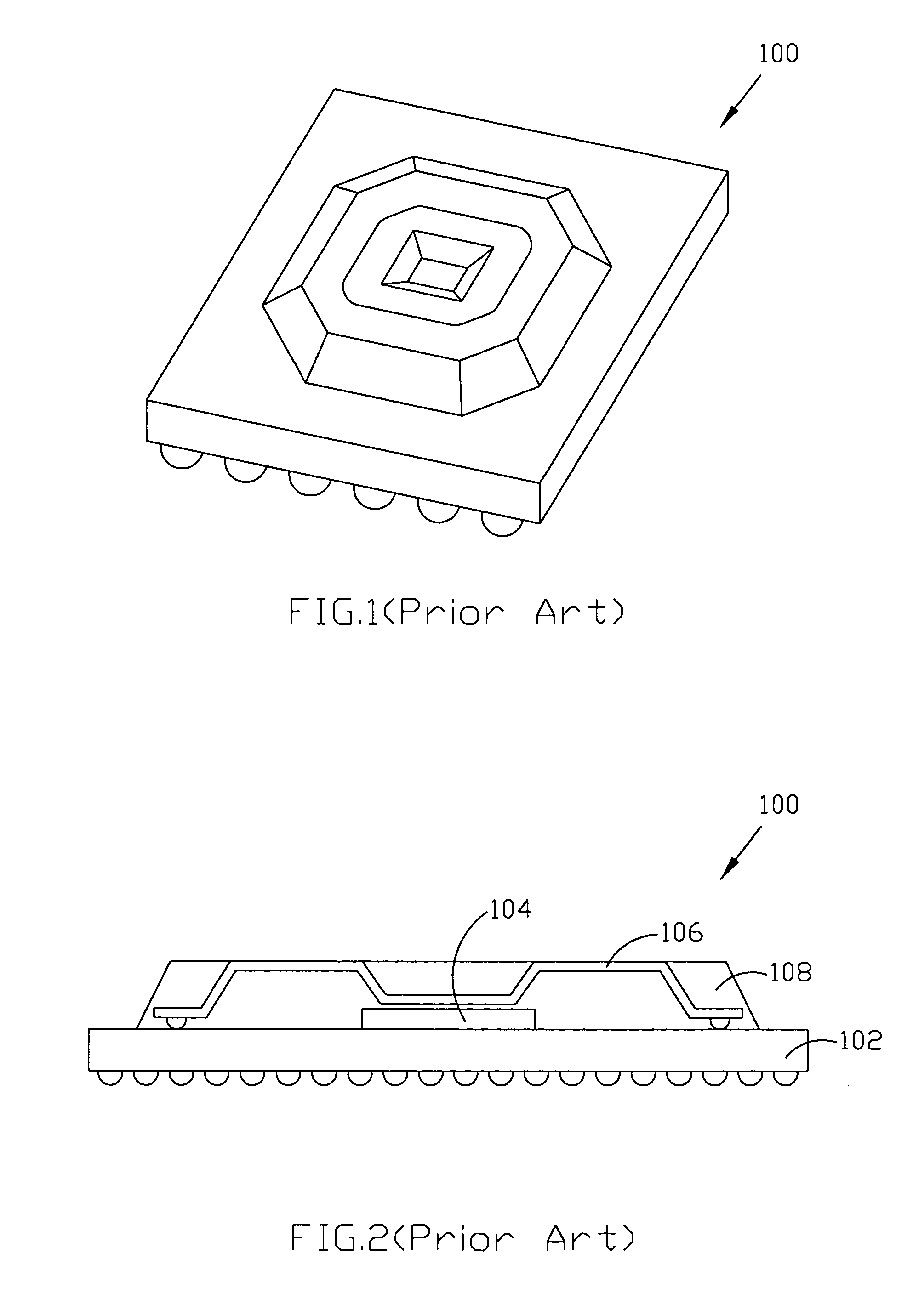
So the ball grid array package device 100 can not get good heat dissipating efficiency.
Nevertheless, the defect of this technique is that if the die or chip 104 generate a large volume of heat, the heat cannot be removed to the environment sufficiently to reduce the operating temperature of the die or chip 104.

Method used


Image

  • Ball grid array package with heat sink device
  • Ball grid array package with heat sink device
  • Ball grid array package with heat sink device

Examples


Embodiment Construction

[0024]Some sample embodiments of the invention will now be described in greater detail. Nevertheless, it should be recognized that the present invention can be practiced in a wide range of other embodiments besides those explicitly described, and the scope of the present invention is expressly not limited except as specified in the accompanying claims.

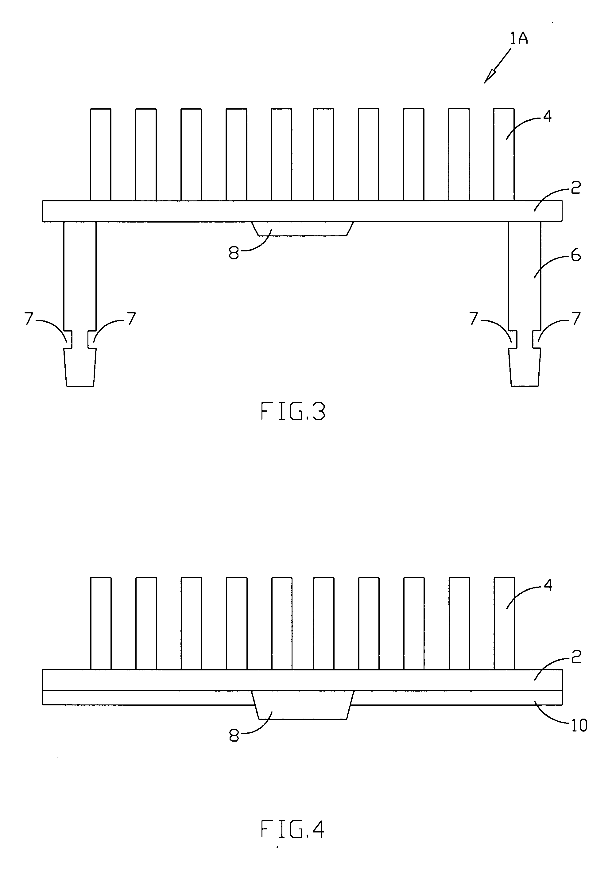
[0025]The present invention provides the package device with modified embedded heat slug to reduce the thermal resistance and to increase the heat dissipating capability. The package device can be a ball grid array package device. FIG. 3 through FIG. 7 illustrates the structure, function, and the relationship there-between of the heat sink device, and FIG. 8 represents the heat-dissipating path of the heat sink device of the present invention. FIG. 3 represents the structure of the first heat sink assembly 1A, which includes a first heat dissipating structure 2 and a second heat dissipating structure 4. The second heat dissipating stru...


PUM


Abstract

The present invention provides a heat sink device for the package device to improve the heat dissipating efficiency. The heat sink device includes a first heat sink assembly and a second heat sink assembly. The first heat sink assembly has a first heat dissipating structure, a second heat dissipating structure positioned above first the heat dissipating structure, at least two thermal supports on the backside of the first heat sink assembly and a thermal block on the backside of the first heat sink assembly. The second heat sink assembly has a protruding structure and at least the openings. The first heat sink assembly is fixed with the second heat sink assembly to form a heat sink device by the combination of the thermal supports and the openings. The first heat sink assembly and the second heat sink assembly are attached to the integrated circuit device separately by the thermal block and the protruding structure. This heat sink device provides several heat dissipating pathes by the second heat dissipating structure, the thermal supports, the thermal block, and protruding structure. Therefore, the heat dissipation efficiency of the heat sink device is improved.

Description

BACKGROUND OF THE INVENTION[0001]1. Field of the Invention[0002]The present invention generally relates to a heat sink applied to an integrated circuit, and more particularly to a package device with a heat sink to reduce the thermal resistance and to improve the efficiency of thermal dissipation.[0003]2. Description of the Prior Art[0004]In the electronics and computer industries, it has been well known to employ various types of electronic package devices and integrated circuit chips, such as the PENTIUM central processing unit chip (CPU) manufactured by Intel Corporation. These integrated circuit chips have a pin grid array (PGA) package and are typically installed into a socket. These integrated circuit chips are installed onto a computer circuit board by soldering. These integrated circuit device for example the CPU microprocessor chips, generate a great deal of heat during operation which must be removed to prevent adverse effects. The PENTIUM microprocessor contain millions o...

Claims


Application Information

Patent Timeline
Patent Type & Authority Patents(United States)
IPC IPC(8): H05K7/20H01L23/36H05K1/18H01L23/40
CPCH01L23/4093H01L2924/15311H01L2924/16152
Inventor WU, CHUNG-JULIN, WEI-FENG
Owner SILICON INTEGRATED SYSTEMS
Learn More