Aerosol enhancement device

Inactive Publication Date: 2007-04-17
CLINICAL TECH
View PDF88 Cites 53 Cited by
  • Summary
  • Abstract
  • Description
  • Claims
  • Application Information

AI Technical Summary

Benefits of technology

[0008]The present invention provides an aerosol medication delivery apparatus which incorporates the aforementioned advantages. The inventive device includes a fixed volume holding chamber which is constructed to allow for a uniformly mixed, concentrated bolus of medicated aerosol to be delivered with each breath. The device further includes a universal inlet, so that any standard small volume nebulizer, as well as any standard MDI, may be utilized therewith. Also filtration can be added to address contaminated patient air and aerosol. A one-way valve is positioned in the patient mouthpiece, to help control the loss of aerosol, and thereby reduce waste.
[0013]In yet another aspect of the invention, a spacer member is provided which is usable with a mouthpiece, for dispensing medicated aerosol to a patient. The inventive spacer member comprises an outer body which defines an interior volume or mixing chamber. An inlet port is disposed in the spacer member for receiving a medicated aerosol from an exterior source into the mixing chamber. An air inlet port is also disposed in the spacer member for receiving air into the mixing chamber. An outlet port is provided for dispensing a mixture of the medicated aerosol and inlet air from the mixing chamber into the mouthpiece. Advantageously, a one-way valve is disposed in the air inlet port, for ensuring that there is no loss of medicated aerosol from the mixing chamber.

Problems solved by technology

However, the Grimes device, as is typical for prior art devices, is plagued with problems typical of such devices.
These problems include, for example, nonuniform concentrations of medication, resulting in difficulties in regulating patient dosage, and significant waste of medication.
Additionally, the Grimes device is relatively complex, so that it is expensive to manufacture and difficult to use.
Of course, such devices are even less suited to satisfactory regulation of the medication being delivered to the patient than the Grimes device, because there is substantially no ability to uniformly mix the medication with entrained fluid, such as air, before delivery to the mouthpiece on which the patient is inhaling.

Method used


Image

  • Aerosol enhancement device
  • Aerosol enhancement device
  • Aerosol enhancement device

Examples


Embodiment Construction

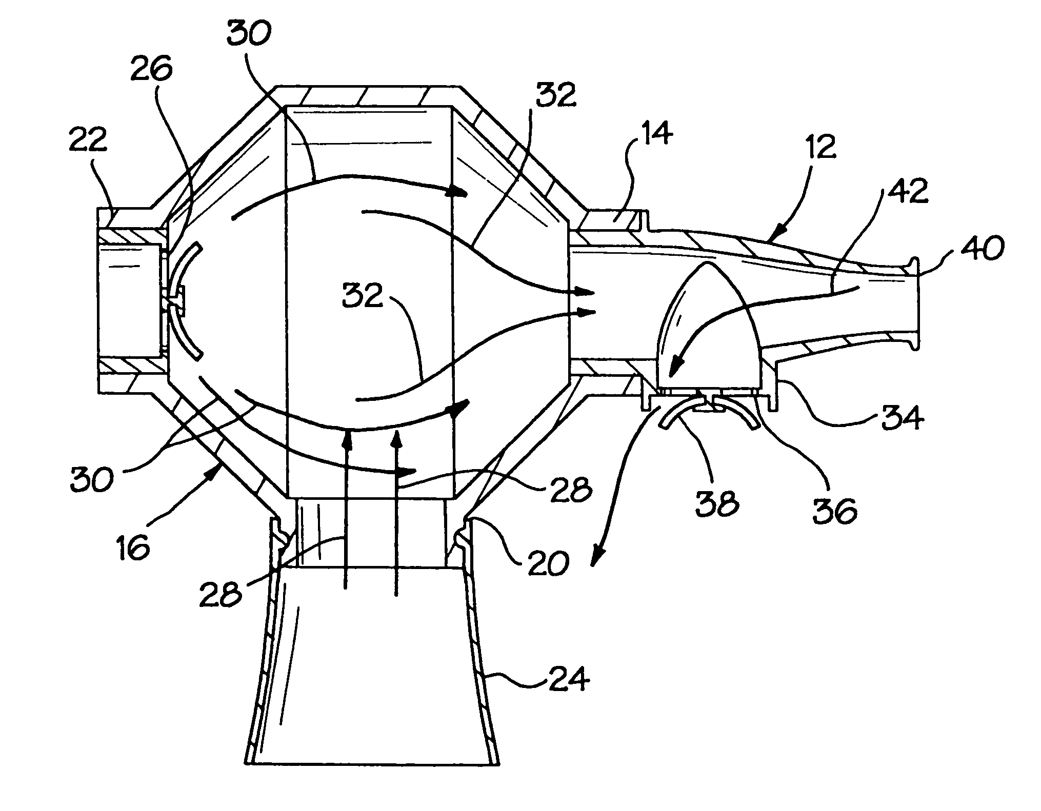
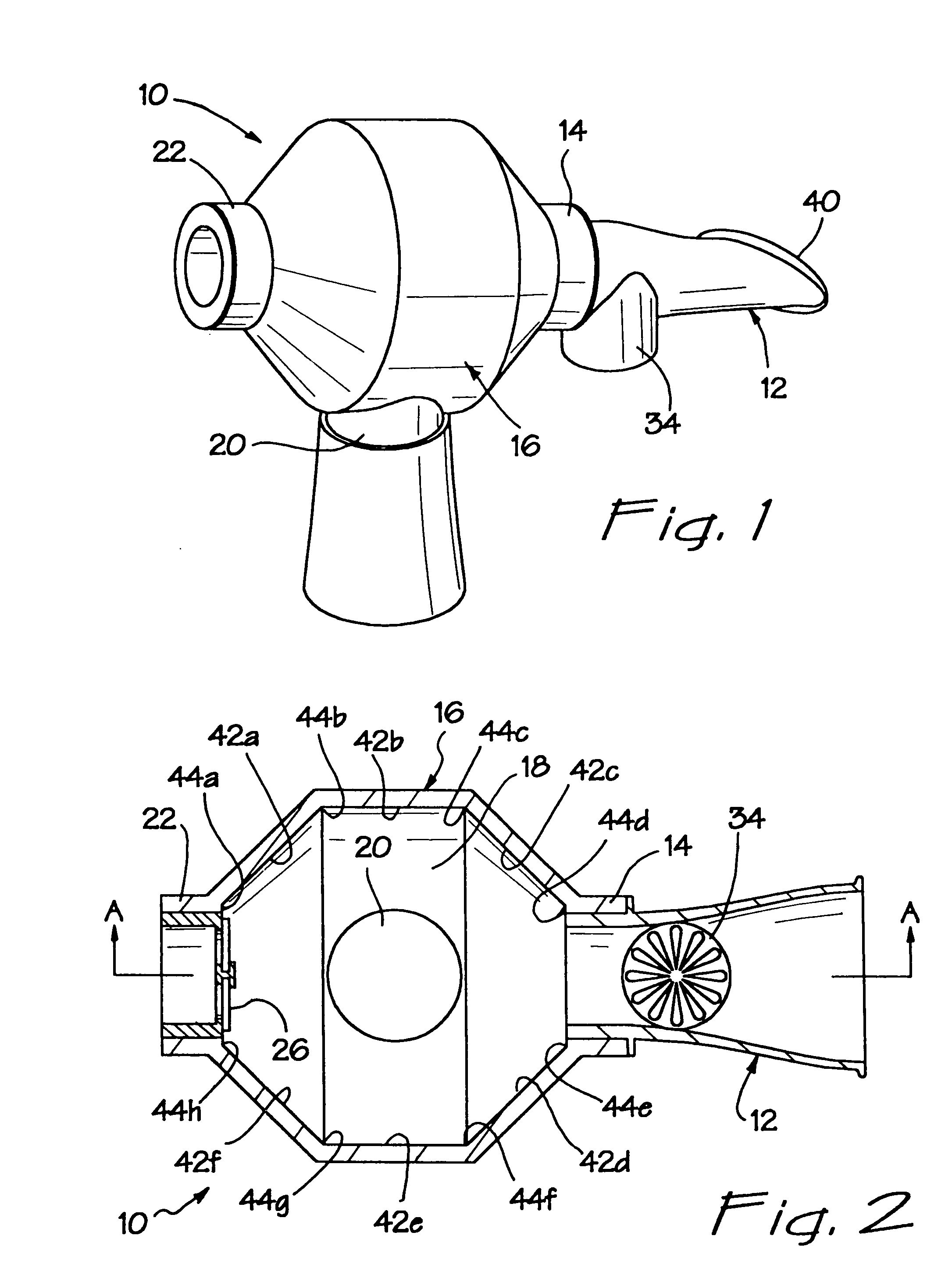
[0031]Referring now more particularly to FIGS. 1–6, there is shown a first embodiment of the inventive aerosol enhancement device 10. The device 10 comprises a mouthpiece 12 which is fluidly attached to a mouthpiece port 14 on a tower or spacer body 16. The spacer body 16 comprises an interior volume or mixing chamber 18 and two additional inlet ports 20 and 22, which communicate with the mixing chamber 18. In the illustrated embodiment, the ports 14 and 22 are disposed on opposing ends of the spacer body 16, with the port 20 disposed between the ports 14 and 22, on the bottom of the body 16 and at a transverse orientation with respect to the ports 14 and 22.

[0032]As shown particularly in FIGS. 5 and 6, the aerosol enhancement device 10 may be configured for use with a metered dose inhaler (MDI), as shown in FIG. 5, or a nebulizer, as shown in FIG. 6. Traditionally, an MDI is positioned “in-line” with the patient's mouth, so that the delivered medication flows directly through the c...


PUM


Abstract

An aerosol medication delivery apparatus includes a fixed volume holding chamber which is constructed to allow for a uniformly mixed, concentrated bolus of medicated aerosol to be delivered with each breath. The device further includes a universal inlet, so that any standard small volume nebulizer, as well as any standard metered dose inhaler (MDI), may be utilized therewith. Also filtration can be added to address contaminated patient air and aerosol. A one-way valve is positioned in the patient mouthpiece, to help control the loss of aerosol, and thereby reduce waste.

Description

[0001]This application is a continuation-in-part of application Ser. No. 09 / 610,801, also entitled Aerosol Enhancement Device, filed on Jul. 6, 2000 now U.S. Pat. No. 6,363,932, which is commonly assigned and herein expressly incorporated by reference.BACKGROUND OF THE INVENTION[0002]This invention relates generally to an improved aerosol inhalation device, and more particularly to an aerosol enhancement device which is usable in combination with both a nebulizer and a metered dose inhaler.[0003]Aerosol inhalation devices, for the purpose of delivering medication, entrained in an aerosol spray, to a patient using inhalation therapy, as an alternative to oral medications such as capsules or pills, or to injected medications, are well known in the art. For example, U.S. Pat. No. 4,210,155 to Grimes is representative of the prior art. In the Grimes patent there is disclosed a fixed volume mist accumulation chamber for use in combination with a nebulizer and a tee connection of an inhal...

Claims


Application Information

Patent Timeline
IPC IPC(8): A61M11/00A61MB65D83/34A61M11/02A61M15/00A61M16/08A61M16/10B05B9/03B65D83/36
CPCA61M15/0086A61M15/0015A61M15/0016A61M15/0018A61M16/0808A61M2206/16A61M16/1055A61M16/0093A61M16/1065
Inventor JOHNSON, ROBERTDUBOSE, ROBERT
Owner CLINICAL TECH
Why Eureka
Try Eureka