
System and method for reducing NOx emissions in an apparatus having a diesel engine

a technology of diesel engine and emission control system, which is applied in the direction of mechanical equipment, electric control, machines/engines, etc., can solve the problems of reducing exhaust temperature, affecting the performance of various aftertreatment devices, and affecting the efficiency of diesel engines, so as to reduce improve engine efficiency , the effect of reducing the concentration of nox

Active Publication Date: 2007-04-17
FORD MOTOR CO
View PDF9 Cites 9 Cited by
  • Summary
  • Abstract
  • Description
  • Claims
  • Application Information

AI Technical Summary

Benefits of technology

The patent text describes a method for controlling emissions in diesel engines by using low temperature diesel combustion and an aftertreatment device. The method involves early injection of fuel into the combustion chamber to reduce NOx and particulate matter emissions. The aftertreatment device includes a catalyst that converts NOx and particulate matter. The method also involves controlling the temperature of the aftertreatment device by adjusting the timing of fuel injection and exhaust valves. The technical effect of this patent is to provide a more efficient and effective method for controlling emissions in diesel engines.

Problems solved by technology

Controlling emissions in diesel engines has posed significant challenges to the automotive industry.
While early homogenization combustion may improve engine efficiency and decrease concentrations of NOx and particulate emissions, it may also lead to lower exhaust temperatures, which may negatively impact the performance of various aftertreatment devices, particularly when a diesel engine is operating at a light load and / or at idle.

Method used


Image

  • System and method for reducing NOx emissions in an apparatus having a diesel engine
  • System and method for reducing NOx emissions in an apparatus having a diesel engine
  • System and method for reducing NOx emissions in an apparatus having a diesel engine

Examples


Embodiment Construction

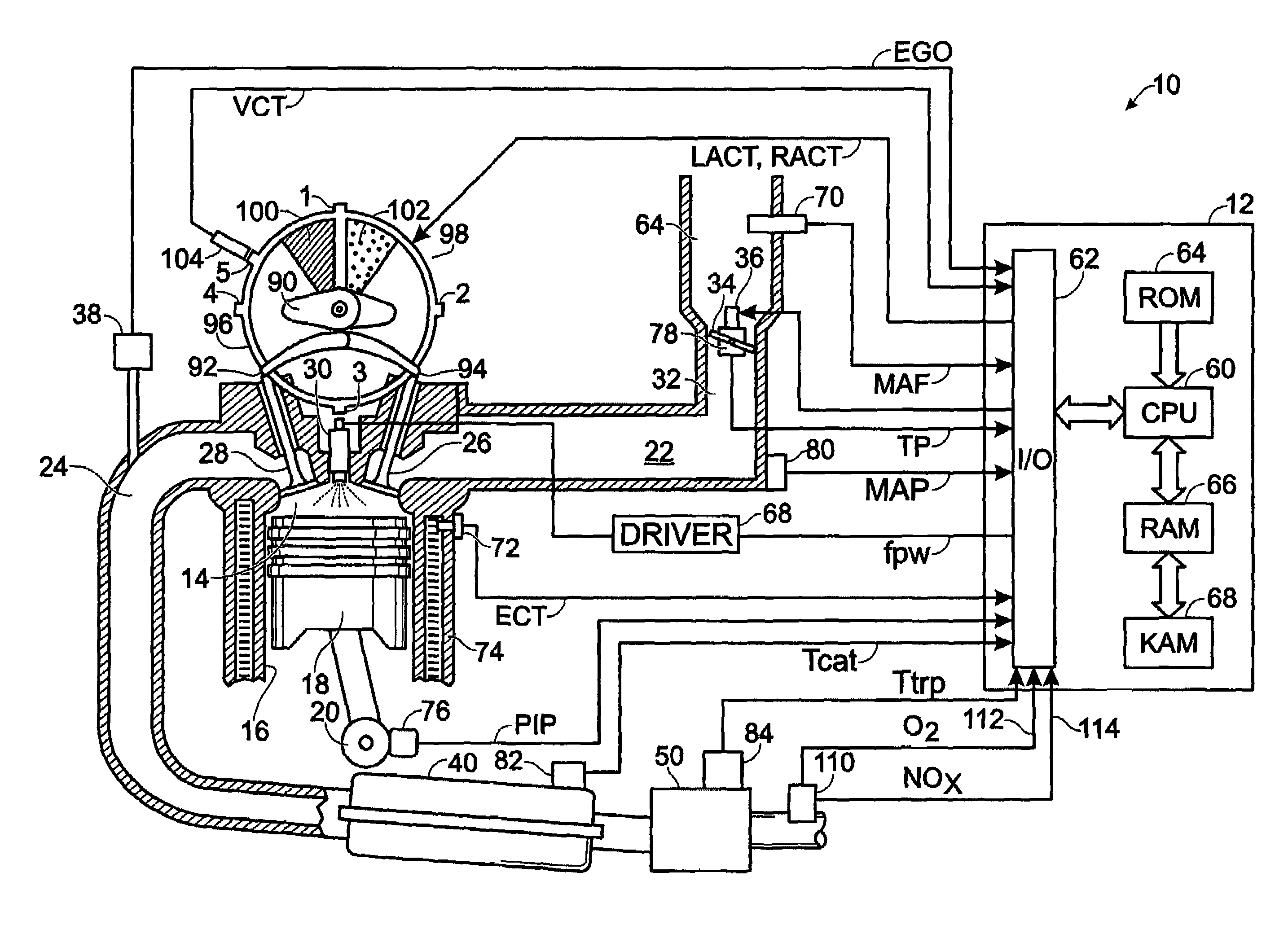
[0015]FIG. 1 shows, generally at 10, an exemplary embodiment of one cylinder of a multi-cylinder diesel engine, intake and exhaust paths connected to that cylinder, and an exemplary embodiment of a camshaft having a variable timing mechanism for controlling the valves of the cylinder. It will be appreciated that the configuration of engine 10 is merely exemplary, and that the systems and methods described herein may be implemented in any other suitable engine.

[0016]Continuing with FIG. 1, engine 10 is controlled by electronic engine controller 12. Combustion chamber, or cylinder, 14 of engine 10 is shown including combustion chamber walls 16 with piston 18 positioned therein and connected to crankshaft 20. Combustion chamber 14 is shown communicating with intake manifold 22 and exhaust manifold 24 past intake valve 26 and exhaust valve 28. Fuel injector 30 is coupled to combustion chamber 14 for delivering injected fuel directly therein in proportion to the fuel pulse width (fpw) si...


PUM


Abstract

In a mechanical apparatus having a diesel engine including a combustion chamber, an intake valve for passing air into the combustion chamber, and an exhaust valve for passing exhaust from the chamber, the mechanical apparatus also having an aftertreatment device configured to treat emissions from the diesel engine, a method of operating the engine is disclosed, wherein the method includes performing at least one combustion in the combustion chamber with a first quantity of fuel, determining a temperature of the aftertreatment device, and if the temperature of the aftertreatment device is equal to or below a preselected temperature threshold, then performing at least one combustion in the combustion chamber with a second, greater quantity of fuel and varying at least one of an intake valve timing and an exhaust valve timing relative to a default valve timing to cause at least one of a compression loss and a pumping loss.

Description

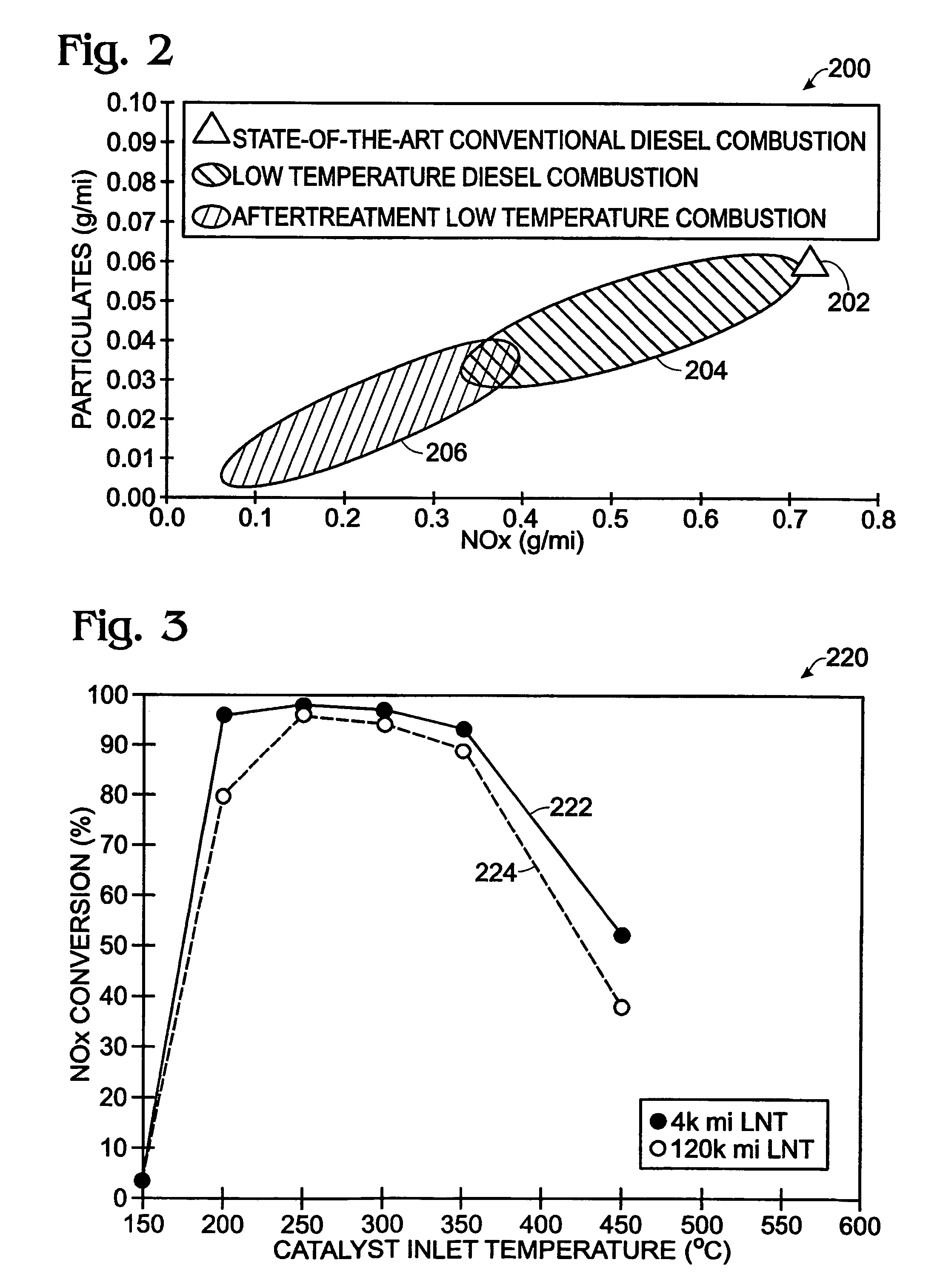
TECHNICAL FIELD[0001]The present application relates to the field of automotive emission control systems and methods.BACKGROUND AND SUMMARY[0002]Controlling emissions in diesel engines has posed significant challenges to the automotive industry. Several different methods of controlling emissions from diesel engines have been proposed. One type of method is generally known as low temperature diesel combustion, and may be used to control the emissions of substances including but not limited to nitrogen oxides (“NOx”) and particulate matter.[0003]One method of performing low temperature diesel combustion is to perform an early injection of fuel into the combustion chamber of the engine so that the fuel bums at lower temperatures. The lower combustion temperatures produce lower concentrations of NOx, particulate, and other byproducts.[0004]The early injection of fuel allows the fuel to mix more thoroughly with air than ordinary diesel combustion, and is therefore sometimes referred to a...

Claims


Application Information

Patent Timeline
Patent Type & Authority Patents(United States)
IPC IPC(8): F02B3/00F01N3/00
CPCF01N3/0814F01N13/009F01N3/101F02D37/02F02D41/0275F01N3/0842F01N2250/12F01N2250/14F01N2430/08F01N2430/085F01N2430/10F01N2560/025F01N2560/06F01N2560/14F02D41/3035F02D2041/001F02D2200/0804Y02T10/22Y02T10/12
Inventor LEONE, THOMASBERGER, ALDOERING, JEFF
Owner FORD MOTOR CO
Learn More