
Image-reading apparatus

a technology of image-reading apparatus and reading device, which is applied in the direction of lighting and heating apparatus, optical radiation measurement, instruments, etc., can solve the problems and inability to control a light emitting amount for every color, so as to prevent the deviation of detected values, prevent the deterioration of color balance of output image, and prevent the effect of deterioration of color balan

Inactive Publication Date: 2007-04-10
KONICA MINOLTA PHOTO IMAGING
View PDF1 Cites 8 Cited by
  • Summary
  • Abstract
  • Description
  • Claims
  • Application Information

AI Technical Summary

Benefits of technology

This approach stabilizes image reading by ensuring equal base light amounts and synchronized operations across colors, preventing color balance deterioration without increasing apparatus complexity or size, resulting in high-quality image reproduction.

Problems solved by technology

It is impossible, however, to control a light emitting amount for every color, when the halogen lamp is employed for the light emitting source.
Accordingly, there has been a problem that the color balance of the image reproduced from the read image data would be deteriorated due to the following reasons.
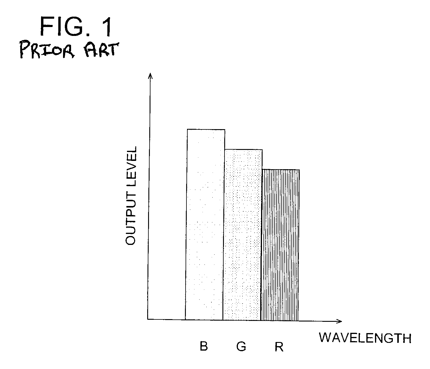
As shown in FIG. 1, since the base penetrated light amount (defined as an amount of light only penetrated through a substrate, a subbing layer, a filter layer, etc., irrespective of contents of the image, namely, a penetrated light amount at a non-image area) varies with the wavelength range of the light emitted from the light emitting source, namely, colors (here, R (Red), G (Green), B (Blue)), the base penetrated light amounts of colors R, G, B could not coincide with each other, resulting in a deterioration of the color balance.
As a result, however, the apparatus becomes complicated and large-sized.
This causes a deficiency of deteriorating the color-balance of the reproduced image outputted on the basis of the acquired data.

Method used


Image

  • Image-reading apparatus
  • Image-reading apparatus
  • Image-reading apparatus

Examples


first embodiment

[0047]As shown in FIG. 4, in the first embodiment, reading control means B1 controls the CCD operation so that the centers of the photo receiving times of colors R, G, B, IR coincide with each other during one scanning time interval. It is applicable either to make the center of the photo receiving time coincide with that of one scanning time or not to make.

[0048]When the base penetrated light amounts are exhibited as shown in FIG. 1, reading control means B1 adjusts not only the photo receiving amounts by lengthening the photo receiving times in order of B→G→R corresponding to the output levels decreasing in order of B→G→R, but also the center of the photo receiving time corresponding to the scanning operation for the photographic image. Further, since the light source of the halogen lamp, etc., generally exhibits a high intensity of infrared light, the photo receiving time is set at a short time to avoid the saturation of the CCD.

second embodiment

[0049]As shown in FIG. 5, in the second embodiment, reading control means B1 conducts the photo receiving operation for each color CCD by using a plurality of pulses over one scanning interval to control it so that the integrated value of each data of the photo receiving amount becomes a photo receiving amount necessary for each wavelength region. Further, as shown in FIG. 5, one scanning interval is divided into right and left regions, and the borderline, at which a pulse area of the right region is equal to that of the left region, is established as a center time point of the pulse integrated value. In this photo receiving operation for each color CCD, it is applicable either to make the center time points coincide with each other or not to make.

[0050]Further, it is also applicable that reading control means B1 conducts a controlling operation, so that, within a light receiving time in a wavelength region, in which a light receiving time for making the light receiving amount neces...

third embodiment

[0081]In the third embodiment, reading control means B1 independently controls the start and stop of the light emitting action of the each color LED. As shown in FIG. 8(d), reading control means B1 controls the CCD operation so that the centers of the photo emitting times of colors R, G, B, IR coincide with each other, while maintaining the light emission output levels of colors R, G, B, IR at level E. It is applicable either to make the center of the photo emitting time coincide with that of one scanning time interval or not to make. According to this embodiment, the center of the photo emitting time of each LED is located at the same time point within one scanning line d (in FIG. 8, t1=t2, or t1≠t2). Accordingly, since the center of integrating the distribution of light receiving amount received by the light receiving means for each color overlaps with that of another color, it becomes possible to prevent the deviation of the detected value of the density of the read image for eve...


PUM


Abstract

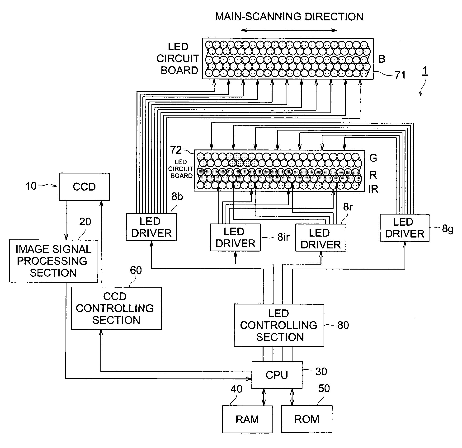
There is described an image-reading apparatus to acquire image data by reading a scanned image comprising an image sensor having a light emitting means and a photo receiving means for receiving a light emitted from the light emitting means, and a reading control means for controlling the image sensor. The photo receiving means separately acquires light amount data in a plurality of wavelength regions, and the reading control means independently controls a start and a stop of each of light receiving operations of the photo receiving means conducted in the plurality of wavelength regions. Further, there is also described an image-reading apparatus to acquire image data by reading a scanned image comprising an image sensor having a plurality of light emitting means, light emitting wavelength regions of which are different from each other, and photo receiving means for receiving light emitted from the plurality of light emitting means, and a reading control means for controlling the image sensor, and the reading control means independently controls a start and a stop of each of light emitting operations conducted by the plurality of light emitting means.

Description

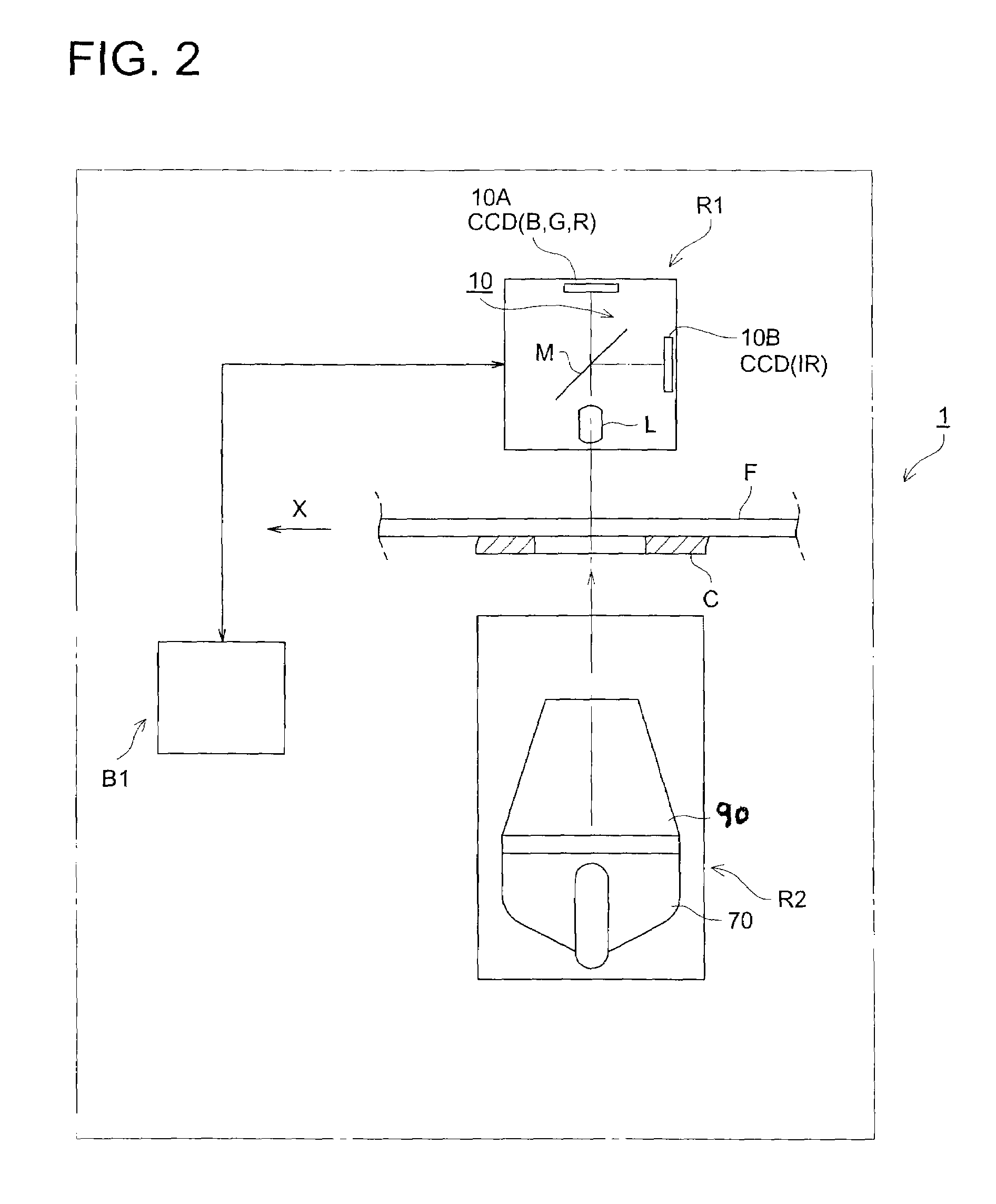
BACKGROUND OF THE INVENTION[0001]The present invention relates to an image-reading apparatus.[0002]In recent years, there has been well-known an image-reading apparatus, which reads an image recorded on a photographic film or a photographic print (hereinafter, referred to as a photographic image, for the general term of them) by means of an image sensor to acquire image data. For instance, a film scanner, being an example of such the image-reading apparatus, acquires the image data by conducting the steps of: irradiating light, emitted from a light emitting means such as a halogen lamp, etc., onto the developed photographic film on which the image is already formed, while conveying the photographic film; photo-electronically reading the light penetrated through the photographic film by means of a photo detecting element, such as a CCD (Charge Coupled Device), a line sensor, etc.; and applying an analogue-to-digital conversion processing (hereinafter, referred to as A / D conversion pr...

Claims


Application Information

Patent Timeline
Patent Type & Authority Patents(United States)
IPC IPC(8): H01L27/00
CPCH04N1/48
Inventor MURAOKA, TAKETOH
Owner KONICA MINOLTA PHOTO IMAGING
Learn More