
Concrete test cylinder mold cap

a concrete test cylinder and mold cap technology, applied in the direction of machines/engines, manufacturing tools, instruments, etc., can solve the problems of many concrete test cylinders that are not uniform, prior art does not ensure that every sample is of the same height, and many concrete test cylinders are non-planar

Inactive Publication Date: 2007-04-10
STALLONE DOMINICK V
View PDF18 Cites 7 Cited by
  • Summary
  • Abstract
  • Description
  • Claims
  • Application Information

AI Technical Summary

Benefits of technology

[0025]A feature of the present invention is to provide a method and apparatus for reproducibly producing a concrete test sample that is uniform in height, diameter and overall smoothness.
[0026]Another feature of the present invention is to provide such a sample by a method that is quick and easy to use and also relatively inexpensive.
[0030]Yet another feature of the present invention is to provide a cap that has internal threads for threadedly engaging external threads on a concrete test cylinder mold thereby increasing the rotatability of the cap upon the concrete test cylinder mold.
[0033]Yet another feature of the present invention is to increase the efficiency and simplicity of producing a uniform and reproducible concrete test sample through the placement of a cap with at least one excretion hole onto a concrete test sample mold.
[0035]Another feature of the present invention is to provide a method for molding a concrete test cylinder, comprising the steps of pouring concrete into a concrete test cylinder mold to a point where the poured concrete extends above a top portion of the concrete test cylinder mold. A cap having at least one radial trough and at least one excretion hole is placed on the top portion of the concrete test cylinder mold. The cap is manually pressed and rotated against the top portion of the concrete test cylinder mold thereby channeling excess concrete through the radial troughs for excretion through the excretion hole in the cap. In addition, the radial trough smoothes the surface of the poured concrete within the concrete test cylinder mold. Prior to the initial set of the concrete in the concrete test cylinder mold, the cap is rotated upon the top portion of the concrete test cylinder mold in order to separate the cap from the poured concrete within the concrete test cylinder mold. After the cap is separated from the poured concrete, the poured concrete is allowed to cure within the concrete test cylinder mold for a predetermined time. Then, the cured concrete is removed from the concrete test cylinder mold thereby producing a uniform and reproducible concrete test cylinder.

Problems solved by technology

The problem with the prior art concrete test cylinders that are produced in conventional concrete test cylinder molds is that the concrete test cylinders produced are non-uniform.
The prior art does not ensure that every sample is of the same height, diameter and level.
As a result, many concrete test cylinders are non-planar or have a oval diameter at the top of the mold.
Accordingly, the accuracy of the test of the concrete test cylinder is reduced since the overall compressive strength of the concrete test cylinder can be erratic due to the non-uniformity of the concrete test cylinder.

Method used


Image

  • Concrete test cylinder mold cap
  • Concrete test cylinder mold cap
  • Concrete test cylinder mold cap

Examples


Embodiment Construction

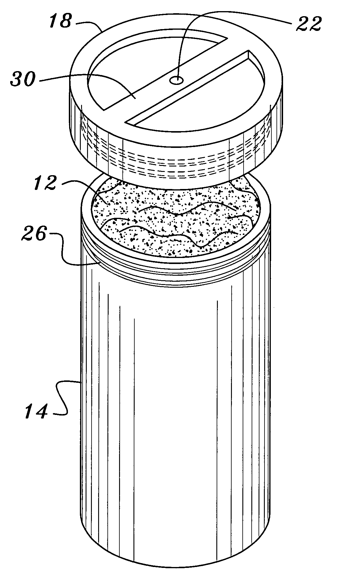
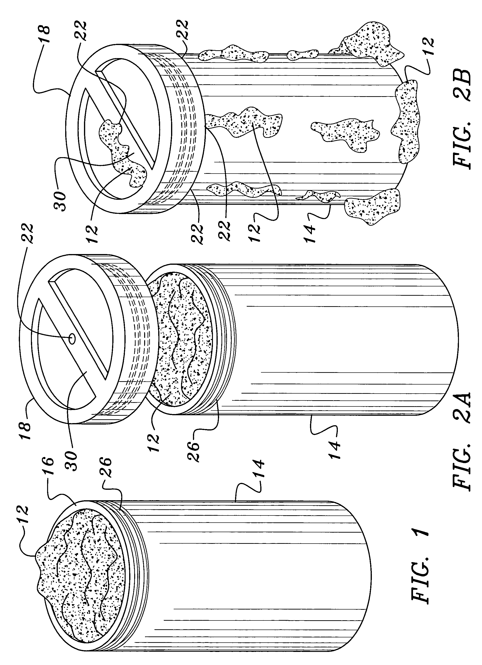
[0051]Reference will now be made to the drawings. FIG. 1 shows a standard concrete test cylinder mold 14 filled with concrete 12. The concrete 12 has been added to the concrete test cylinder mold 14 in compliance with the standards set forth by the American Society for Testing Materials (ASTM) for sampling fresh concrete 12.

[0052]As shown in FIG. 1 the poured concrete 12 is uneven and extends approximately one quarter of an inch above the top portion 16 of the concrete test cylinder mold 14. In the prior art, the excess concrete 12 that extends above the top portion 16 of the concrete test cylinder mold 14 is manually struck off with a trowel or a float. The prior art method results in varying flatness, height and other non uniformities to the concrete test cylinders that are produced using this prior art method.

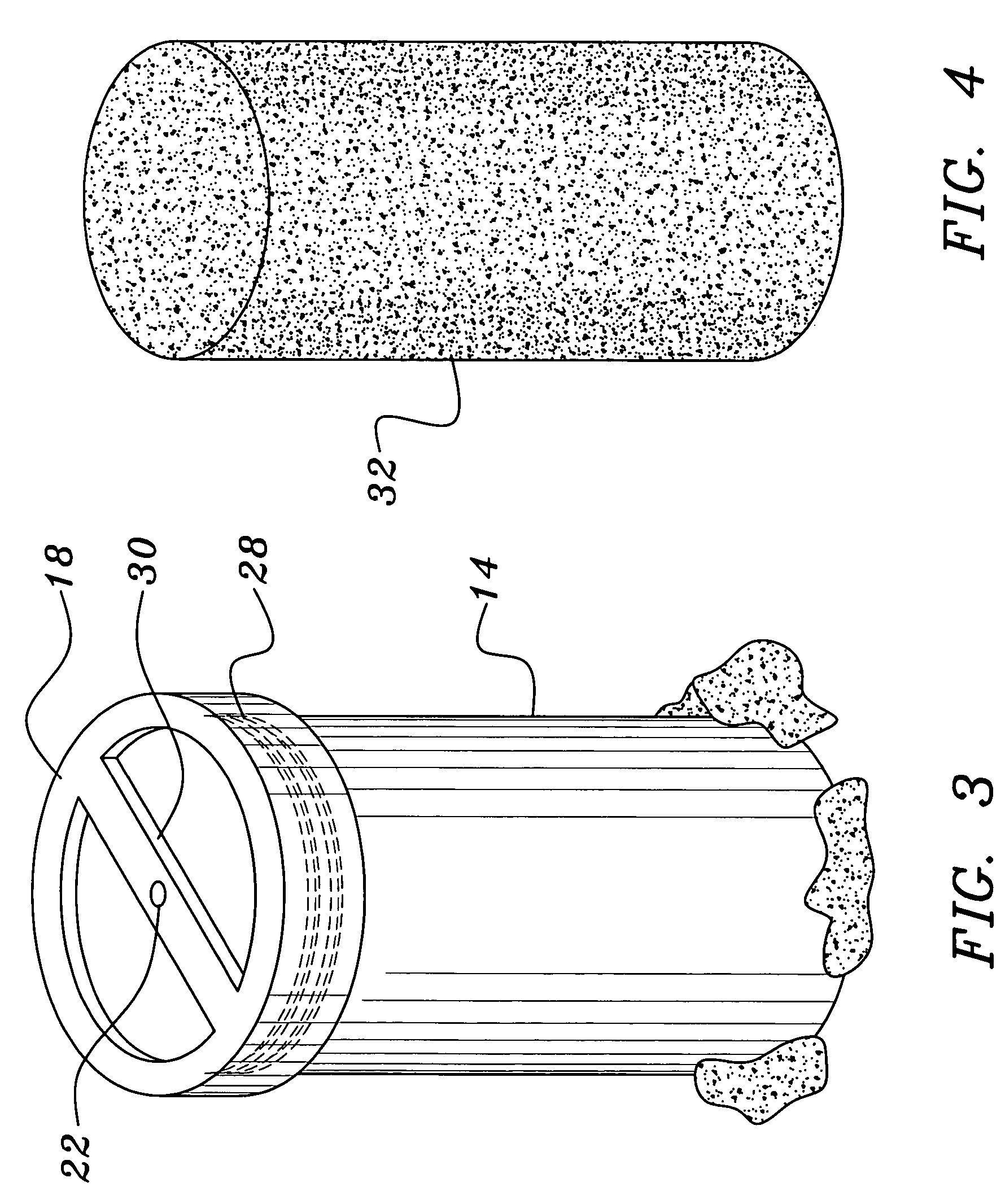
[0053]Whereas, as best shown in FIG. 2A, the present invention provides a method for making reproducible and uniform concrete test cylinders. As shown in FIG. 1, the fresh c...


PUM

PropertyMeasurementUnit
diameteraaaaaaaaaa
diameteraaaaaaaaaa
strengthaaaaaaaaaa

Abstract

A method and apparatus for molding a reproducible uniform concrete test cylinder. Concrete is poured into a concrete test cylinder mold. A cap having at least one excretion hole is placed on the top portion of the concrete test cylinder mold. The cap is pressed against the top portion of the concrete test cylinder mold thereby excreting excess concrete through the excretion hole in the cap. After the cap is separated from the poured concrete, the poured concrete is allowed to cure within the concrete test cylinder mold for a predetermined time. Then, the cured concrete is removed from the concrete test cylinder mold thereby producing a uniform and reproducible concrete test cylinder.

Description

CROSS REFERENCES TO RELATED APPLICATIONS[0001]This application claims priority from and is a divisional of commonly owned U.S. Utility patent application Ser. No. 09 / 923,189, filed Aug. 6, 2001 now U.S. Pat No. 6,776,387, entitled: CONCRETE TEST CYLINDER MOLD CAP, this Utility patent application incorporated by reference herein.FIELD OF THE INVENTION[0002]This invention relates to concrete testing methods and apparatus and, more particularly, provides a method and apparatus for producing a reproducible concrete test cylinder.DESCRIPTION OF THE BACKGROUND ART[0003]In the construction of highways, buildings, and other structures utilizing concrete, it is necessary from time to time to test the strength of a sample of the poured concrete to ensure that it has sufficient structural strength required for a particular installation. The most common method of testing concrete has been to take a sample of fresh concrete from a mix at a construction site.[0004]Specifically, fresh concrete is ...

Claims


Application Information

Patent Timeline
Patent Type & Authority Patents(United States)
IPC IPC(8): B28B3/00G01N33/38B28B7/00
CPCB28B7/0094Y10S249/04
Inventor STALLONE, DOMINICK V.
Owner STALLONE DOMINICK V
Learn More