
Intake amount control apparatus of internal combustion engine

a technology of intake valve and amount control, which is applied in the direction of electrical control, combustion engines, valve arrangements, etc., can solve the problems of deteriorating fuel economy, so-called torque shock, and engine torque reduction, and achieve the effect of reducing the influence of the intake valve, reducing the amount of intake valve lift, and large capacity

Active Publication Date: 2007-04-10
TOYOTA JIDOSHA KK
View PDF3 Cites 5 Cited by
  • Summary
  • Abstract
  • Description
  • Claims
  • Application Information

AI Technical Summary

Benefits of technology

Enables prompt and smooth transition to fuel cut control, reducing sudden engine torque changes and improving fuel economy by reducing engine torque before fuel cut control is executed.

Problems solved by technology

It is to be noted herein that although the fuel economy can be improved by executing the fuel cut control, the execution of this control causes no more combustion of fuel and naturally results in reduction in engine torque.
Therefore, if the engine torque prior to the execution of the fuel cut control is large, the fuel cut control results in occurrence of a so-called torque shock.
Furthermore, if the fuel cut control is executed after the engine torque has sufficiently reduced, the sharp change in engine torque can be eliminated or reduced, but the start of the fuel cut control is delayed, so that deteriorated fuel economy is inevitable.

Method used


Image

  • Intake amount control apparatus of internal combustion engine
  • Intake amount control apparatus of internal combustion engine
  • Intake amount control apparatus of internal combustion engine

Examples


first embodiment

[0018]A first embodiment in which the intake amount control apparatus of an internal combustion engine of the invention is embodied will be hereinafter described.

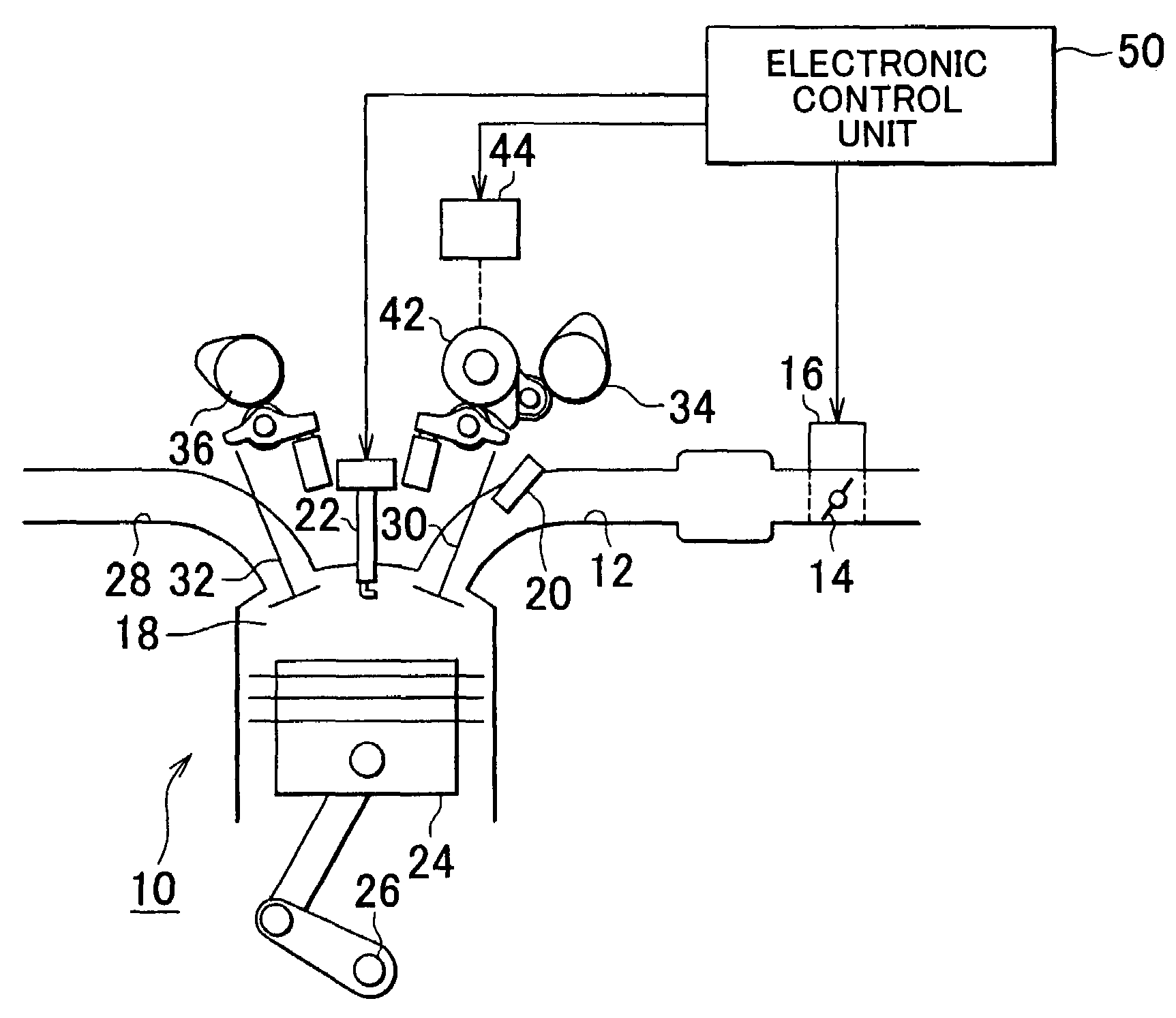
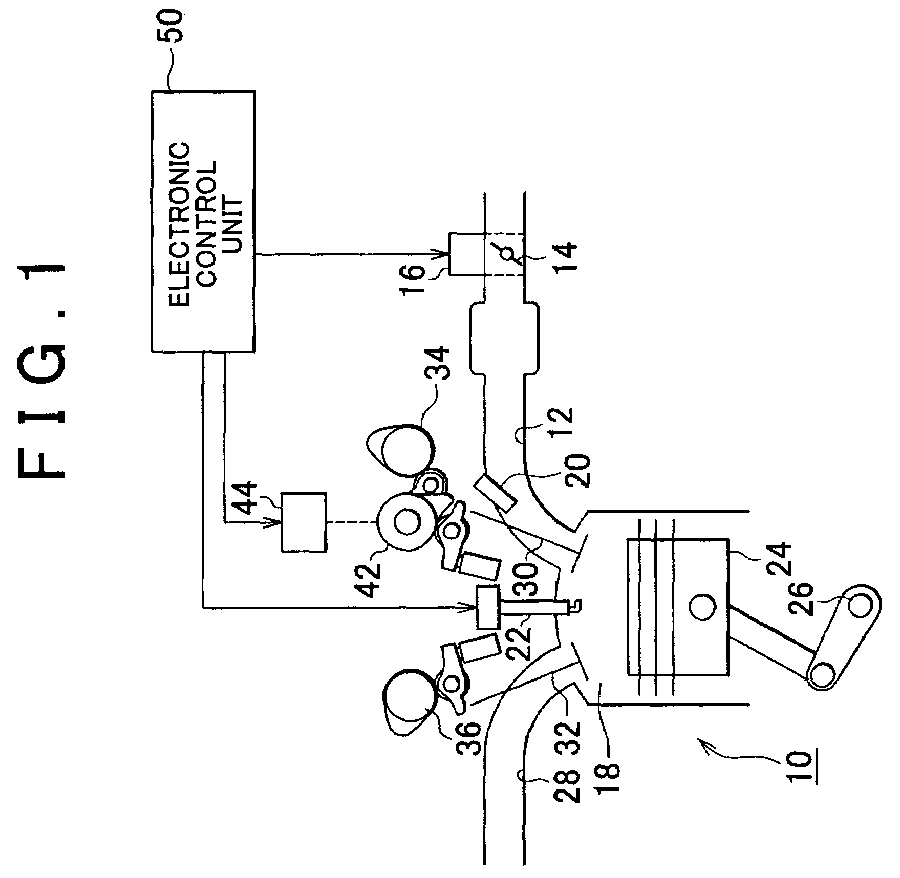
[0019]FIG. 1 shows an overall constitution of an intake amount control apparatus in accordance with this embodiment. As shown in FIG. 1, an intake passageway 12 of an internal combustion engine 10 is provided with a throttle valve 14. A throttle motor 16 is connected to the throttle valve 14. Through the drive control of the throttle motor 16, the opening amount of the throttle valve 14 (throttle opening amount TA) is adjusted, so that the amount of air taken into a combustion chamber 18 through the intake passageway 12 is adjusted. Furthermore, the intake passageway 12 is provided with a fuel injection valve 20. This fuel injection valve 20 injects fuel into the intake passageway 12, as exhaust gas.

[0020]In the combustion chamber 18 of the internal combustion engine 10, a mixture formed by intake air and injected fuel is i...

second embodiment

[0043]A second embodiment in which the intake amount control apparatus of an internal combustion engine of the invention is embodied will be described below.

[0044]This embodiment and the first embodiment differ from each other in the following respects. The intake amount control apparatus in accordance with the first embodiment executes the lift amount changing control so that, prior to execution of the fuel cut control, the lift amount VL of the intake valve 30 becomes smaller than at the time of the normal idle operation where the fuel cut control is not executed. On the other hand, the intake amount control apparatus of the second embodiment executes a throttle control along with execution of the lift amount changing control so that the throttle opening amount TA becomes smaller than at the time of the normal idle operation where the fuel cut control is not executed.

[0045]The overall constitutions of the internal combustion engine and its peripheral appliances to which the intake...


PUM


Abstract

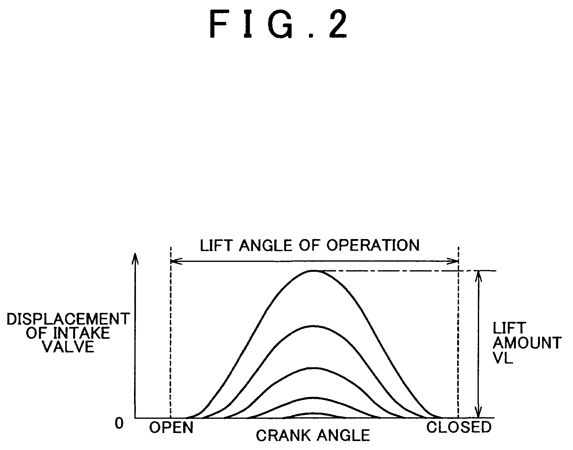
An intake amount control apparatus of an internal combustion engine in accordance with the invention includes a control portion that controls an opening amount of a throttle valve provided in an intake passageway of the internal combustion engine and operation of a lift amount changing mechanism capable of changing a lift amount of an intake valve. The control portion controls the operation of the lift amount changing mechanism so that, prior to execution of a fuel cut control at the time of an engine deceleration, the lift amount of in intake valve becomes smaller than at the time of a normal engine idle operation where the fuel cut control is not executed.

Description

INCORPORATION BY REFERENCE[0001]The disclosure of Japanese Patent Application No. 2004-299014 filed on Oct. 13, 2004, including the specification, drawings and abstract, is incorporated herein by reference in its entirety.BACKGROUND OF THE INVENTION[0002]1. Field of the Invention[0003]The invention relates to an intake amount control apparatus of an internal combustion engine in which a fuel cut control is executed at the time of engine deceleration.[0004]2. Description of the Related Art[0005]In internal combustion engines, the amount of intake is adjusted through the adjustment of the opening amount of a throttle valve provided in an intake passageway, and the amount of fuel corresponding to the amount of intake is injected into an engine combustion chamber. This technology is disclosed in, for example, Japanese Patent Application Laid-Open Publication No. JP-A-08-074639. Furthermore, at the time of engine deceleration, a so-called termed fuel cut control that temporarily stops th...

Claims


Application Information

Patent Timeline
Patent Type & Authority Patents(United States)
IPC IPC(8): F02D11/10
CPCF01L13/0063F02D13/023F02D41/0002F02D41/0005F02D41/123F02D2041/002Y02T10/42Y02T10/18Y02T10/12Y02T10/40
Inventor MUTO, HARUFUMIKAGOSHIMA, KAKUJIIDO, YUICHIRO
Owner TOYOTA JIDOSHA KK
Learn More