
Snare drum device

a snare drum and device technology, applied in the direction of screws, threaded fasteners, instruments, etc., can solve the problem of difficult removal of fasteners, and achieve the effect of difficult removal

Active Publication Date: 2007-04-03
SCOTT BARBARA J
View PDF11 Cites 6 Cited by
  • Summary
  • Abstract
  • Description
  • Claims
  • Application Information

AI Technical Summary

Benefits of technology

The solution effectively maintains the drum's sound and structure by preventing loosening of screws during vibration, reducing the likelihood of screw loss and ensuring secure attachment.

Problems solved by technology

In these self-locking bolts, tension rods, or fasteners, a portion of the helical screw thread is replaced with a pliant member such as a polymer, and when the fastener is tightened, the polymer friction-fits to the threaded hole within the attachments means or nuts, rendering the fastener difficult to remove.

Method used


Image

  • Snare drum device
  • Snare drum device
  • Snare drum device

Examples


Embodiment Construction

[0017]A difficulty in the above prior art system is that the combination of vibration causing by use of the drum and tension applied by the bolts, or by the tension rods, often leads to disengagement of the attachment means, or disengagement of the nuts from the tension rods. In other words, after use, the nuts or bolts tend to unscrew, leading to a modification of the drum sound or even disassembly of the drum.

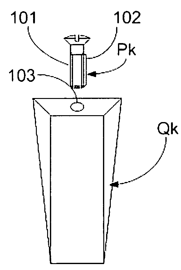
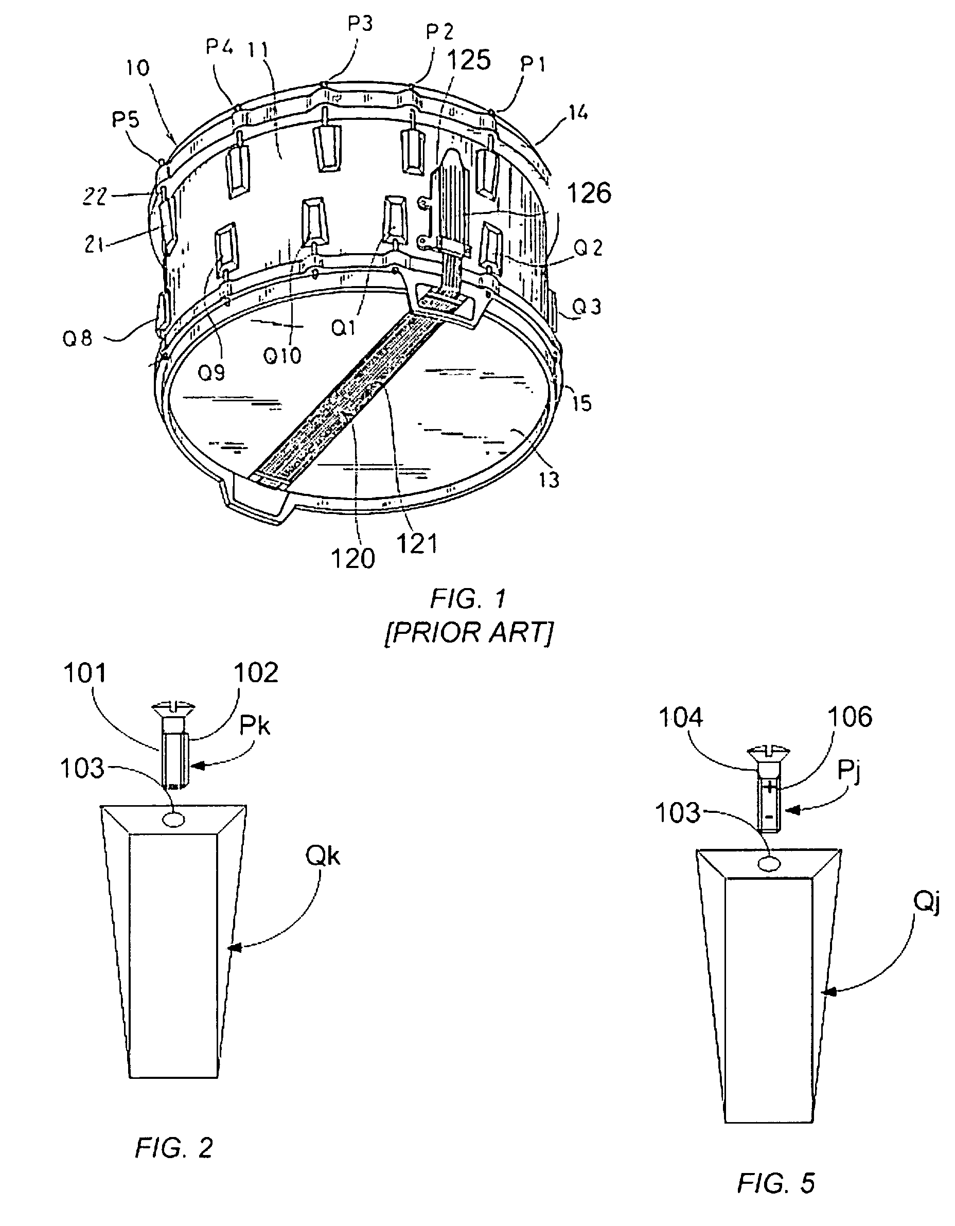
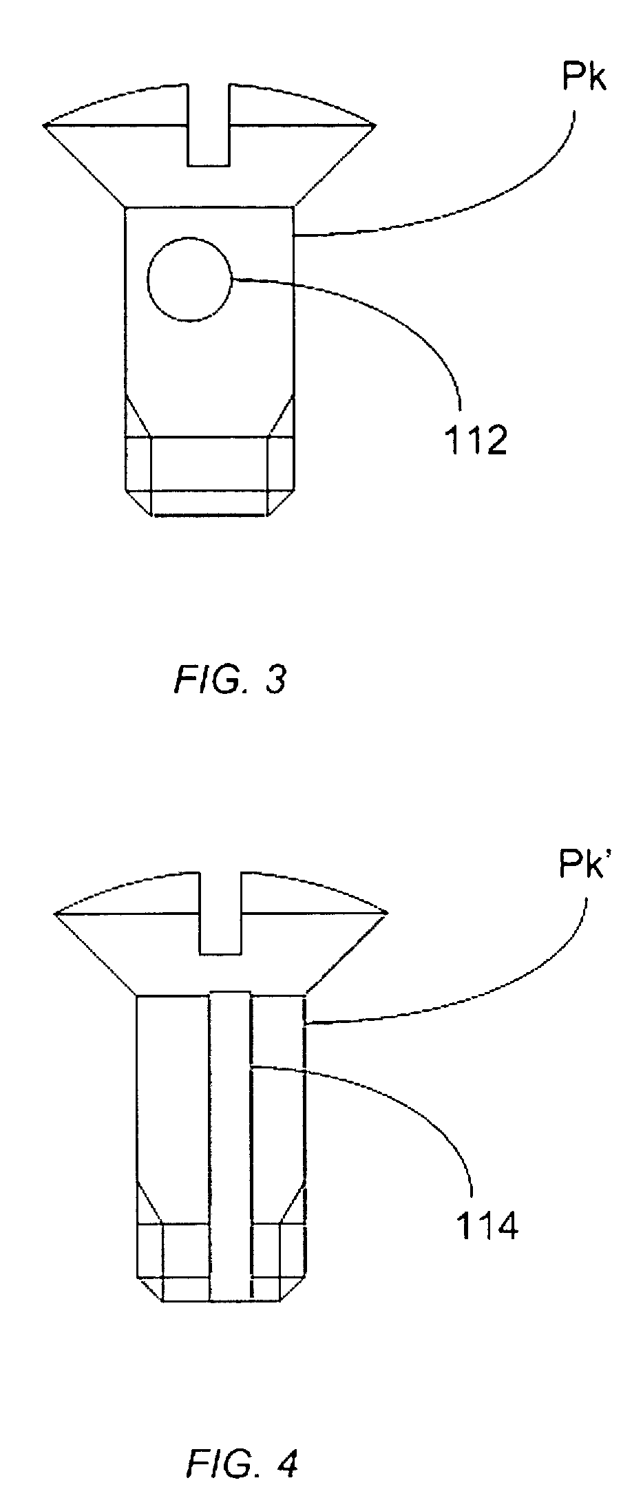
[0018]In the current snare drum, the threaded screw may be a threaded locking screw as is shown in FIG. 2. Appropriate self-locking screws may be such as those produced by the Long-Lok company of Cincinnati, Ohio. In these self-locking fasteners Pk, a portion of the helical screw thread 101 is replaced with a polymer 102, and when the fastener is tightened, the polymer friction-fits to the threaded hole 103 within Qk, rendering the fastener Pk difficult to remove.

[0019]This has a beneficial effect in the current situation. The vibration of the drum during use or otherwise no ...


PUM


Abstract

A device for tension rods or attachment bolts for snare drums. The threaded tension rod or bolt may be a threaded locking bolt. In this way, the vibration caused by use of the drum does not lead to disengagement of the attachment means, or disengagement of the nuts from the tension rods. In these self-locking bolts, tension rods, or fasteners, a portion of the helical screw thread is replaced with a pliant member such as a polymer, and when the fastener is tightened, the polymer friction-fits to the threaded hole within the attachments means or nuts, rendering the fastener difficult to remove.

Description

CROSS-REFERENCE TO RELATED APPLICATIONS[0001]This application is a U.S. Provisional Patent Application Ser. No. 60 / 560,577, filed Apr. 7, 2004.FIELD OF THE INVENTION[0002]The invention relates to devices for use with snare drums.BACKGROUND OF THE INVENTION[0003]A snare drum is a drum fitted with snares to produce a rattling effect. A snare is any of the cords stretched across the bottom skin of a drum so that when the drum is struck, a rattling sound is made. The cords may be made of, e.g., cable, gut or wire.[0004]A typical snare drum, as described in U.S. Pat. No. 6,172,288, includes a shell having a batter end and an oppositely disposed snare end. A batter head is attached to the batter end by a batter rim and a snare head is attached to the snare end by a snare rim. The batter rim and the snare rim are pulled toward one another by tension rods that are aligned and held in place by passing through lugs that are attached to the shell. The rims are positioned over the batter end an...

Claims


Application Information

Patent Timeline
Patent Type & Authority Patents(United States)
IPC IPC(8): G01D13/02G10D13/02
CPCG10D13/023G10D13/02G10D13/16
Inventor SCOTT, CARL
Owner SCOTT BARBARA J
Learn More