Controller for data recorder

a data recorder and control board technology, applied in the field of data recorders, can solve the problems of data amount ultimately becoming null, buffer memory becoming empty, data recording on optical disc interruption,

Inactive Publication Date: 2007-03-27
SEMICON COMPONENTS IND LLC
View PDF74 Cites 3 Cited by
  • Summary
  • Abstract
  • Description
  • Claims
  • Application Information

AI Technical Summary

Benefits of technology

[0010]It is an object of the present invention to provide a controller for a data recorder that controls data recording in a manner that the continuity of the data is ensured even if the recording of data to a recording medium is interrupted.

Problems solved by technology

If the decrease continues, the data amount ultimately becomes null and the buffer memory becomes empty.
This stops the stream of data to the encoder and causes an interruption in the data recorded on the optical disc.
Thus, if a buffer underrun error occurs, the entire optical disc becomes unusable when employing disc at once, and the track undergoing recording becomes unusable when employing track at once.
This has increased the tendency of the occurrence of buffer underrun errors.
The link blocks decrease the recording capacity of the optical disc.
Further, there are CD-ROM drives that are not capable of handling packet writing.
Such CD-ROM drives cannot reproduce data written to optical discs through packet writing.
For example, packet writing cannot be applied for a CD-DA player.
Thus, a CD-R drive cannot record CD-DA audio data through packet writing.
However, when a buffer underrun error occurs, the data file that was being recorded before the occurrence of the buffer underrun error must be recorded again.
This wastes the recording performed prior to the occurrence of the buffer underrun error and increases the recording time.
However, MD drives have the same problem as CD-RW drives.

Method used


Image

  • Controller for data recorder
  • Controller for data recorder
  • Controller for data recorder

Examples


Embodiment Construction

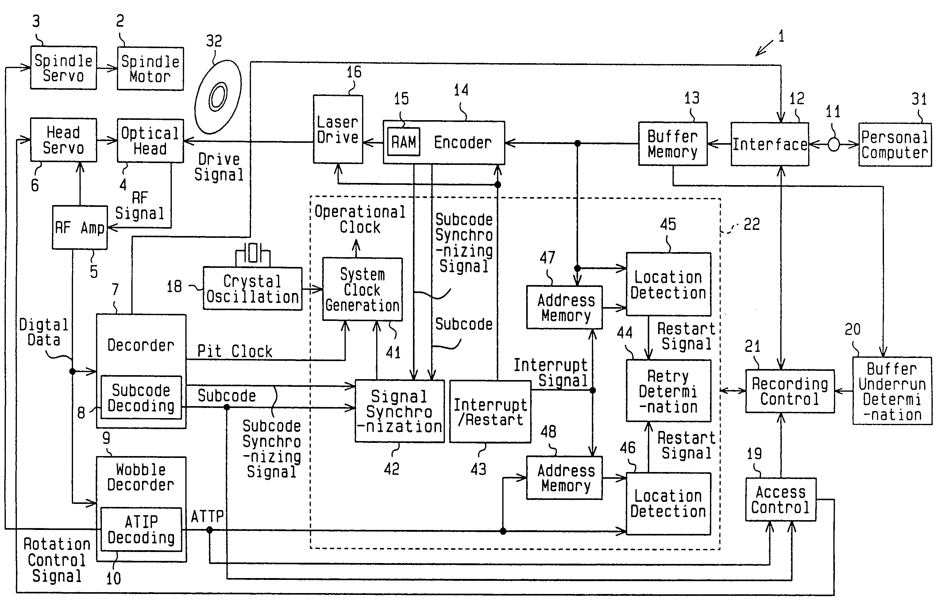
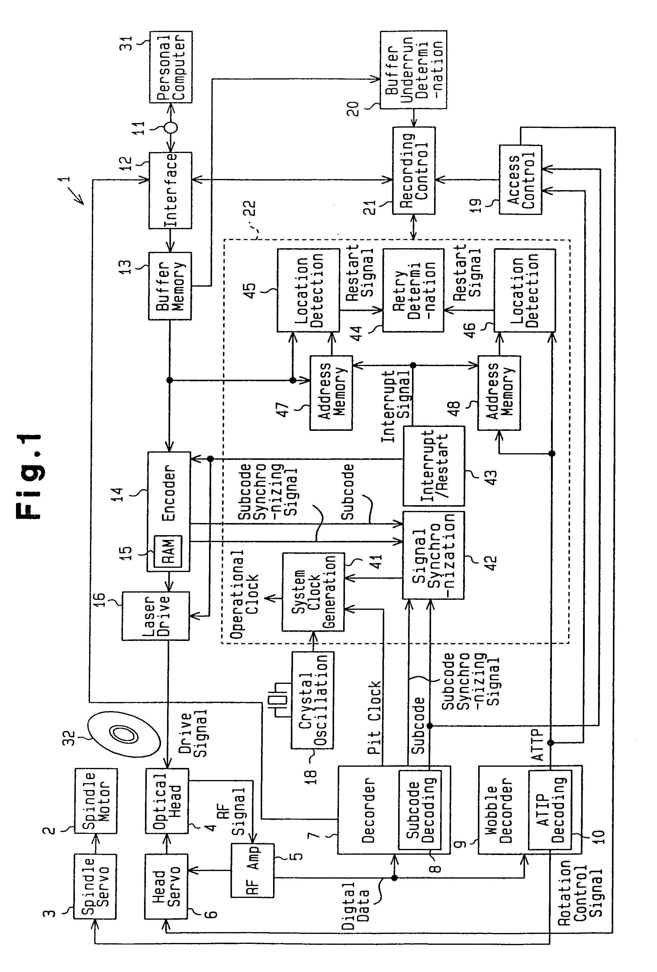
[0026]With reference to FIG. 1, a CD-R drive 1 includes a spindle motor 2, a spindle servo circuit 3, an optical head 4, an RF amplifier 5, a head servo circuit 6, a decoder 7, a subcode decoding circuit 8, a wobble decoder 9, an ATIP decoding circuit 10, an external connection terminal 11, an interface 12, a buffer memory 13, an encoder 14, an encoder internal RAM 15, a laser drive circuit 16, a laser drive circuit internal memory (level memory) 17, a crystal oscillation circuit 18, an access control circuit 19, a buffer underrun determination circuit 20, a recording control circuit 21, and a system control circuit 22. The CD-R drive 1 is connected to a personal computer 31 via the external connection terminal 11 to record data, which is provided from the personal computer 31, on an optical disc 32 that complies with the CD-R standards. Further, the CD-R drive 1 provides the personal computer 31 with data reproduced from the optical disc 32.

[0027]The spindle motor 2 rotates the opt...


PUM


Abstract

A controller for controlling interruptions and restarts when writing data to a recording medium by emitting a laser beam against the recording medium. The controller prevents buffer underrun errors. The laser beam is emitted at a high power level when writing data on the recording medium and at a low power read level when reading data from the medium. The writing of data is interrupted when there is a possibility of a buffer underrun error. When restarting data writing from where the interruption occurred, the laser beam is shifted from the read level to the write level before reaching the location at which the interruption occurred. This guarantees that the laser beam has the required power level when writing is restarted.

Description

BACKGROUND OF THE INVENTION[0001]The present invention relates to a data recorder, and more particularly, to a controller for a data recorder having a buffer memory for storing data provided from an external device and recording the stored data of the buffer memory on a recording medium.[0002]An optical disc recorder records data on an optical disc, which serves as a recording medium. A CD-DA family compact disc-recordable (CD-R) drive is one type of optical disc recorder that is widely used. A CD-R is a so-called write-once optical disc on which data is written only once. The recorded data cannot be physically deleted. A laser beam is irradiated against the optical disc from an optical head of the CD-R drive. The heat of the laser beam melts a dye and forms recording pits on a recording layer of the optical disc. Data is recorded on the disc by changing the reflecting rate of the recording layer.[0003]The optical disc recorder includes a buffer memory and an encoder. The buffer mem...

Claims


Application Information

Patent Timeline
Patent Type & Authority Patents(United States)
IPC IPC(8): G11B5/09G11B7/0045G11B7/125G11B19/04G11B20/10G11B20/12G11B27/10G11B27/11G11B27/19G11B27/30G11B27/36
CPCG11B19/04G11B20/10527G11B20/1217G11B27/10G11B27/36G11B7/126G11B7/0045G11B2220/65G11B27/11G11B27/19G11B27/3027G11B27/3063G11B2020/1074G11B2020/10814G11B2020/10972G11B2020/1267G11B2020/1269G11B2020/1287G11B2220/213G11B2220/216G11B2220/218G11B2220/2529G11B2220/2537G11B2220/2545G11B20/10
Inventor HAYASHI, KOJI
Owner SEMICON COMPONENTS IND LLC
Why Eureka
Try Eureka