Method to make abutted junction GMR head without lead shunting

a technology of abutted junction and read head, which is applied in the field of fabrication of giant magnetoresistive (gmr) read head, can solve the problems of reducing the reducing the sensitivity of the sensor, and reducing the effective usable length and, therefore, its sensitivity, so as to achieve strong output signal, improve free layer sensitivity, and maximize the effect of effective width of the free layer

Inactive Publication Date: 2007-03-27
HEADWAY TECH INC
View PDF12 Cites 3 Cited by
  • Summary
  • Abstract
  • Description
  • Claims
  • Application Information

AI Technical Summary

Benefits of technology

[0008]It is a first object of the present invention to provide an abutted junction GMR bottom spin valve sensor capable of reading narrow trackwidths while producing a strong output signal.
[0009]It is a second object of the present invention to provide an abutted junction GMR bottom spin valve sensor wherein the effective width of the free layer is maximized.
[0010]It is a third object of the present invention to provide an abutted junction GMR bottom spin valve sensor whose free layer sensitivity is improved as a result of the elimination of current shunting.
[0011]The objects of the present invention will be achieved by a method of forming an abutted junction GMR bottom spin valve that significantly reduces or eliminates conducting lead and biasing layer overspreading, which is the undesirable spreading of the conducting lead layer and the biasing layer beyond the abutting junction so as to partially cover the upper surface of the spin valve sensor element and produce current shunting through the sensor. Novel aspects of the method include: 1) formation of a thin dielectric layer between the GMR sensor element capping layer and the double layer of hard magnetic biasing material and conducting lead layer. 2) Adjustment of the angle of the junction so that ion-beam deposition (IBD) of the hard magnetic biasing layer only contacts the junction region of the GMR sensor and the layer does not become deposited on the upper region of the sensor. 3) Ion beam etch (IBE) to remove lead layer overspread.

Problems solved by technology

A disadvantage is that reducing the read width of an abutted junction sensor requires removal of a large portion of the actual element and, therefore, a corresponding reduction of the width of the free layer and loss of signal strength.
This overspread has the disadvantageous effect of reducing the sensitivity of the sensor even beyond the reduction resulting from the narrowed free layer.
The overspread allows sensing current carried by the lead layers to be shunted through lateral edge portions of the free layer, reducing its effective usable length and, therefore, its sensitivity.

Method used


Image

  • Method to make abutted junction GMR head without lead shunting
  • Method to make abutted junction GMR head without lead shunting
  • Method to make abutted junction GMR head without lead shunting

Examples


Embodiment Construction

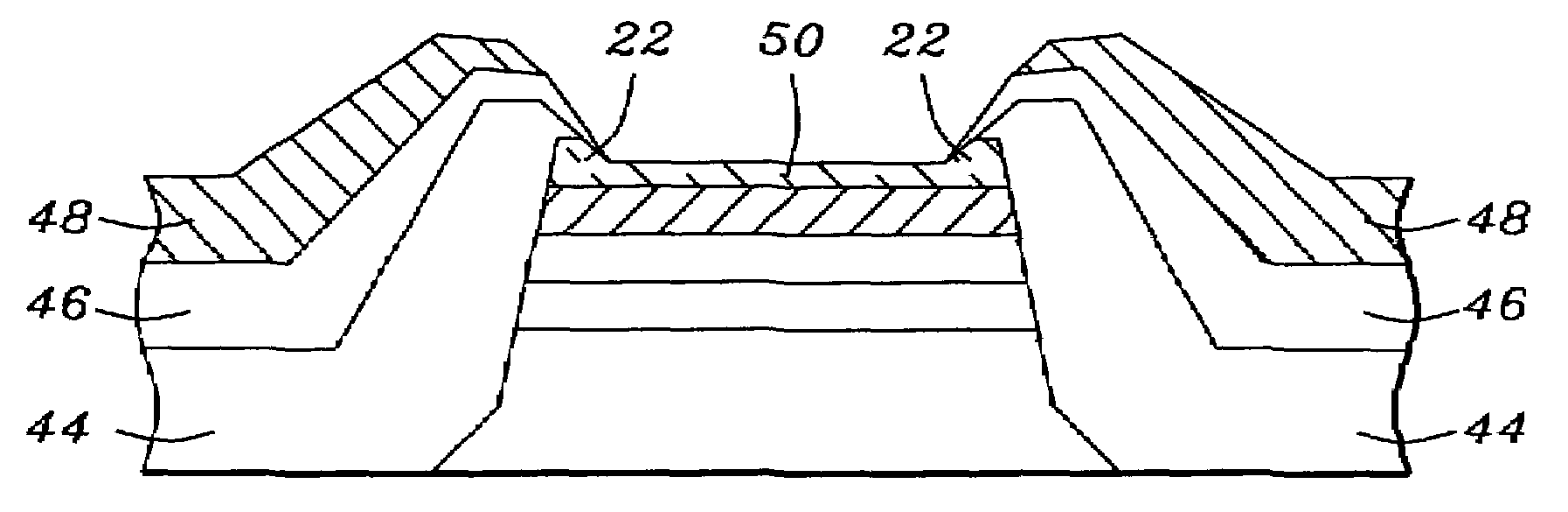
[0018]The preferred embodiment of the present invention is a method for forming an abutted junction bottom spin valve GMR sensor having a minimal amount of conducting lead and hard biasing layer overspreading the upper surface of the sensor element.

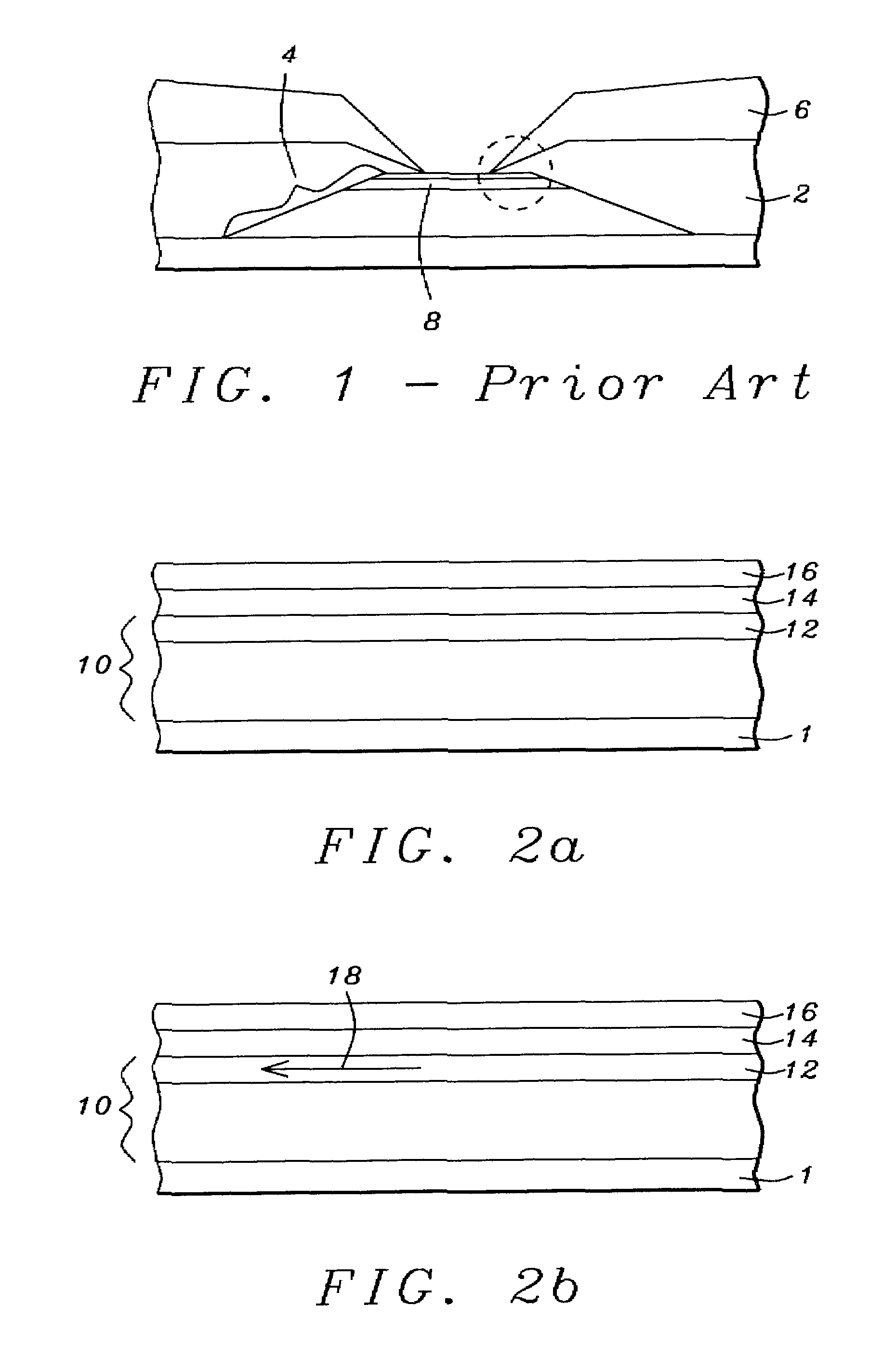
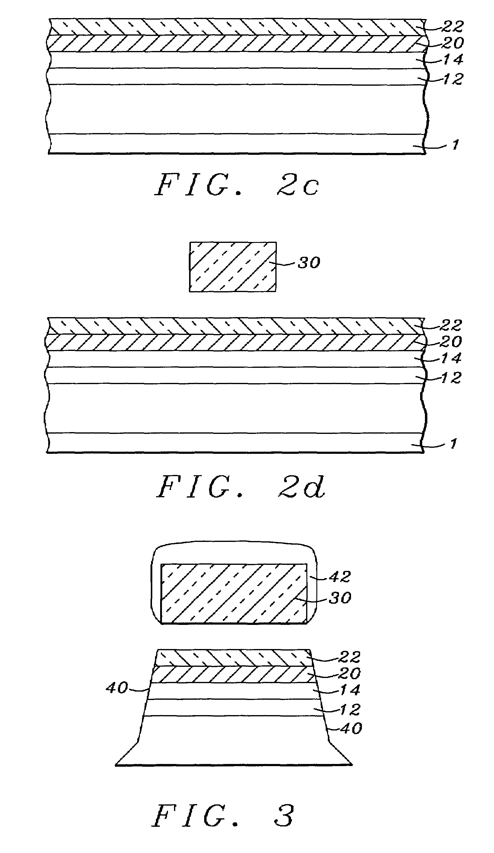
[0019]Referring first to FIG. 2a, there is shown a schematic drawing of the first step required to prepare a GMR bottom spin valve sensor element for the abutted junction provided by the method of the present invention. As can be seen in the drawing, there is formed on a substrate (1) a bottom spin valve sensor element (BSV) (10), having a ferromagnetic free layer (12). A spacer layer (14) is formed on the BSV and a capping layer (16) is formed on the spacer layer. In this embodiment the ferromagnetic free layer (12) can be either a layer of CoFe formed to a thickness of between approximately 15 and 25 angstroms, or a composite layer of CoFe / NiFe, wherein the CoFe portion is of thickness between approximately 5 and 15 angstroms and the Ni...


PUM

PropertyMeasurementUnit
thicknessaaaaaaaaaa
thicknessaaaaaaaaaa
thicknessaaaaaaaaaa

Abstract

A method for forming an abutted junction GMR bottom spin valve sensor in which the free layer has a maximum effective length due to the elimination or minimization of bias layer and conducting lead layer overspreading onto the sensor element and the consequent reduction of current shunting. The overspreading is eliminated by forming a thin dielectric layer on the upper surface of the sensor element. When the biasing and conducting leads are formed on the abutted junction, they overspread onto this layer and the overspread can be removed by an ion-milling process during which the dielectric layer protects the sensor.

Description

BACKGROUND OF THE INVENTION[0001]1. Field of the Invention[0002]This invention relates generally to the fabrication of a giant magnetoresistive (GMR) read head, more specifically to the fabrication of an abutted junction GMR read head having a free layer of maximal effective length resulting from the elimination of overspreading of the biasing and lead layers.[0003]2. Description of the Related Art[0004]Magnetic read heads whose sensors make use of the giant magnetoresistive effect (GMR) in the spin-valve configuration (SVMR) base their operation on the fact that magnetic fields produced by data stored in the medium being read cause the direction of the magnetization of one layer in the sensor (the free magnetic layer) to move relative to a fixed magnetization direction of another layer of the sensor (the fixed or pinned magnetic layer). Because the resistance of the sensor element is proportional to the cosine of the (varying) angle between these two magnetizations, a constant curr...

Claims


Application Information

Patent Timeline
Patent Type & Authority Patents(United States)
IPC IPC(8): G11B5/39G11B5/127G11B5/33G01R33/09G11B5/31
CPCB82Y10/00B82Y25/00G01R33/093G11B5/3903G11B5/3116Y10T29/49044G11B5/3163Y10T29/49052G11B5/313
Inventor HAN, CHERNG-CHYICHEN, MAO-MINWANG, POKANG
Owner HEADWAY TECH INC
Why Eureka
Try Eureka