
System, method and computer program product for collaborative engineering using component and file oriented tools

a technology of applied in the field of system, method and computer program product for collaborative engineering using component and file oriented tools, can solve the problems of weak support of these workflows in current software products, insufficient approach, and particularly in the category of computer aided drafting (cad)

Inactive Publication Date: 2007-03-20
BENTLEY SYST INC
View PDF9 Cites 33 Cited by
  • Summary
  • Abstract
  • Description
  • Claims
  • Application Information

AI Technical Summary

Benefits of technology

The present invention is a system, method, and computer program product for collaborative engineering using component and file oriented tools. The invention allows for the distribution of design elements on multiple servers and machines, and can be scaled up or reconfigured as needed. The invention also allows for the management of file-based data as individual components, with unique identifiers, fields, and programs. The invention can be integrated with existing component and file-based computerized editors, and can be used in multiple editing sessions. The invention can also provide a data management structure for engineering design data, with components representing elements in a file-based computerized editing system. The invention can also include an apparatus for translating file-based data into a plurality of individual components. Overall, the invention provides a more efficient and flexible approach to collaborative engineering.

Problems solved by technology

Engineering projects present a particularly challenging computer information management problem since they are characterized by workflows that involve multiple participants simultaneously making changes to related information.
Current generation software products, particularly those in the computer aided drafting (CAD) category, are weak at supporting these workflows, since they were generally designed to replicate and automate the one-at-a-time nature of drafting boards.
However, that approach is now seen as inadequate.
First, the manual process on which the software design is based has limitations and problems.
For example, coordination between draftspeople requires verbal communication between the draftspeople, which is subject to a breakdown.
Second, the ‘ubiquitous’ nature of electronic information access tends to exacerbate the weaknesses of the manual communications process.
The main drawback of this approach, in a multi-user setting, is that it imposes a fixed limit on how users can collaborate on a project.
By mapping the design concept of a model to the operating system concept of a file, these tools impose file system concepts and limitations on the structure and flow of design work.
This is a bad fit in several respects.
In some cases, changes may affect large parts of the project.
A single engineer may therefore keep a given set of design files locked and out of circulation for long periods of time, blocking the progress of other users whose changes may require write access to one or more of those files.
Clearly, the coarse-grained, file-oriented approach becomes a bottleneck to teamwork.
Equally clearly, even if the unit of information sharing and change-control could be broken down, it would be inappropriate to apply traditional multi-user transaction concurrency rules, which assume relatively quick, isolated changes.
The file-oriented approach also does not address the problem of how to merge the collaborative work of many users on many files into a coherent change to the project.
However, when change is limited to one-at-a-time access to files, there is no chance to express and maintain the interdependencies that exist between files, since it could potentially require that all files be locked in order to make a change to any one.
The merge problem is one aspect of the general problem of documenting, managing, limiting, and potentially reversing the evolution of a design, which is made more complicated when multiple designers are working on it at the same time.
If the unit of change is per-file, then change documentation is harder to do in a sufficiently detailed fashion, and harder to integrate into the editing process itself to guarantee an accurate and useful audit trail.
Add-on products such as workflow managers and product data managers (PDM) do not address this problem of granularity.
The so-called “file-conversion” problem requires that engineering data modeled in the format of one tool be converted to the format of a different tool.
Since different tools and formats have unique features, this conversion cannot always be exact, and a “round trip” will sometimes alter the design in subtle, unintended ways.
The translation mismatch between heterogeneous tools has long been a substantial limitation to integration between design groups within large enterprises and between separate ones.
The main drawbacks to this approach are that (a) it requires mapping engineering design data into database management system (DBMS) constructs, which is not always easy, (b) it requires a separate database management product to be purchased, installed, and administered, and (c) extraction is done once and for all at the start of the session (i.e., everything for the session must be extracted “up-front”).
Some of these products, such as Continuum™, do address the need for a new concurrency model, but are limited by the capabilities of the underlying database management system.
The problem of mapping engineering data into a database format is severe, since the data models of engineering and DBMS tools were developed independently with different goals.

Method used


Image

  • System, method and computer program product for collaborative engineering using component and file oriented tools
  • System, method and computer program product for collaborative engineering using component and file oriented tools
  • System, method and computer program product for collaborative engineering using component and file oriented tools

Examples


Embodiment Construction

[0050]A preferred embodiment of the invention is discussed in detail below. While specific exemplary embodiments are discussed, it should be understood that this is done for illustration purposes only. A person skilled in the relevant art will recognize that other components and configurations can be used without parting from the spirit and scope of the invention.

[0051]Certain terminology is used herein for convenience only and is not to be taken as a limitation on the present invention. In the drawings, the same reference letters are employed for designating the same elements throughout the several figures.

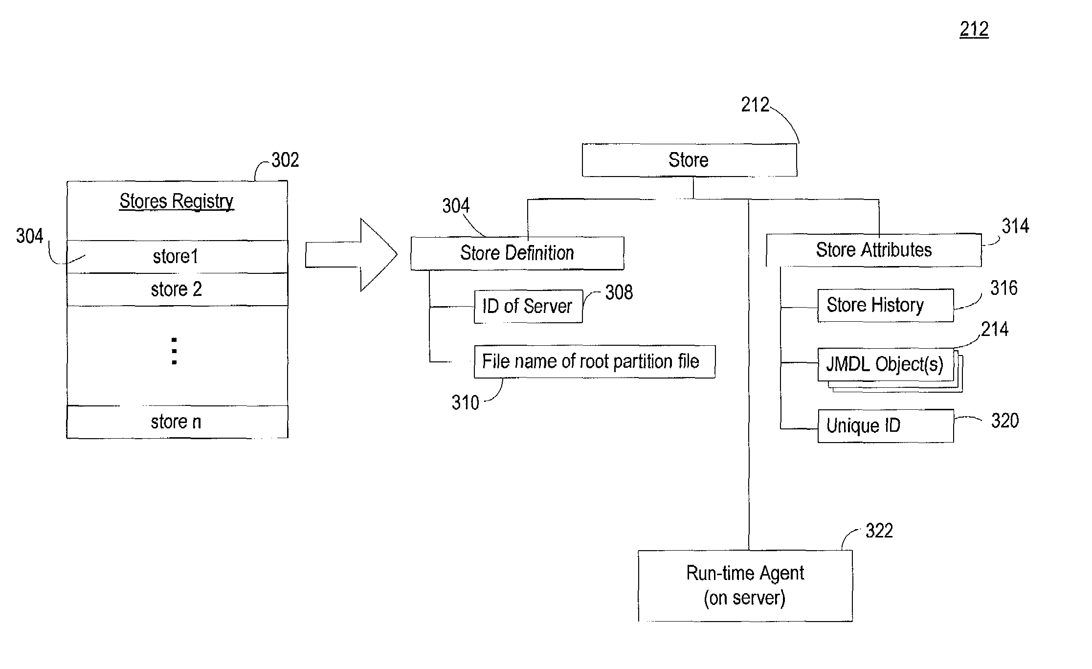
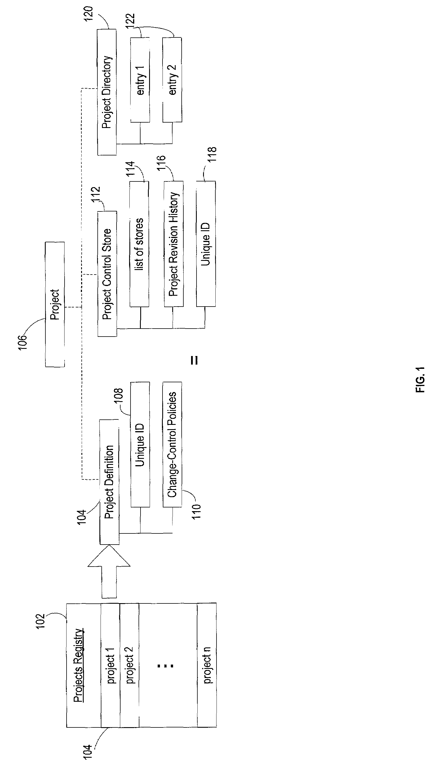
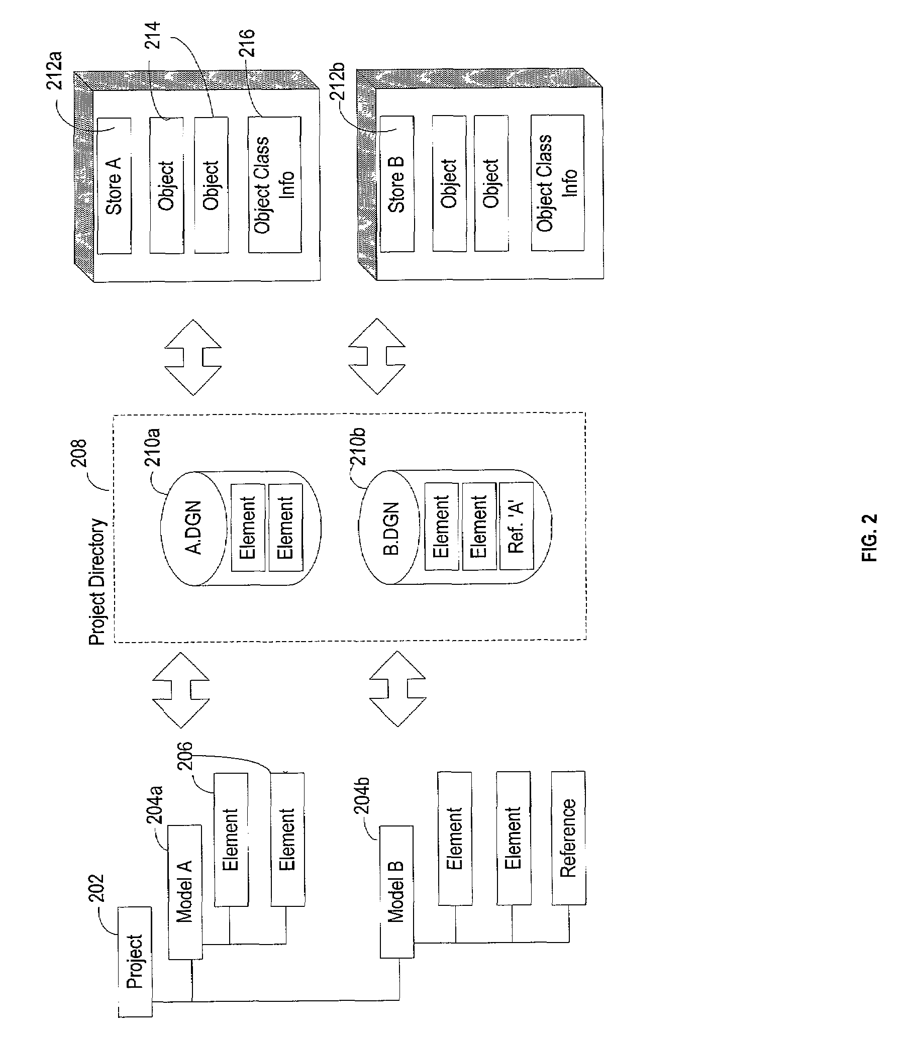
[0052]The present invention subdivides engineering project information into smaller units than drawings so that a more granular unit-of-interchange is presented to project participants. These smaller units are called “components,” which are comprised of data values, data types, programs that manage the data, and connections to other components. The technology is named “ProjectBan...


PUM


Abstract

Conventional file-based engineering design data for an engineering model are represented by a plurality of components. The plurality of components are kept in stores, which reside on servers. Each store contains the components that correspond to the elements of one design file. The stores also maintain a history of changes made to the components. A plurality of client computers are bidirectionally connected to the servers. Each client computer may obtain the current version of the components and may send locally edited versions of the components back to the servers to replace the current versions in the stores. At the client computer, the user interacts with the components using conventional file-based software. Before the locally edited versions of the components are committed to the servers to replace the current versions, a synchronization and merging process occurs whereby the latest version of the components are downloaded to the client computer and are compared to the locally edited version of the components to detect resolvable (compatible) and unresolvable (incompatible) conflicts. The commit process is performed only if no unresolvable conflicts exist between the two versions of the components. To facilitate translation between file-based data and components, a schema is written to “wrap” each of the engineering file formats. Each schema is a set of classes that capture all of the information in the file-based data.

Description

CROSS-REFERENCE TO RELATED APPLICATION[0001]The present application is a continuation-in-part of U.S. patent application Ser. No. 09 / 296,738 filed Apr. 22, 1999, entitled “System for Collaborative Engineering Using Component and File Oriented Tools” of common assignee to the present invention, which claims the benefit of U.S. Provisional Application No. 60 / 102,118, filed Sep. 28, 1998 entitled “ProjectBank—A Technology for Enabling Collaborative Engineering with Component and File-Oriented Tools”, the contents of both are incorporated herein by reference in their entirety.BACKGROUND OF THE INVENTION[0002]1. Field of the Invention[0003]The present invention relates to a system for storing, managing and tracking changes to design information typically created in multi-user, multi-discipline, engineering projects. Specifically, the present invention provides a management tool for tracking and managing multiple simultaneous changes to a project data set in a cohesive, secure, identifiab...

Claims


Application Information

Patent Timeline
Patent Type & Authority Patents(United States)
IPC IPC(8): G06F17/30
CPCG06F17/30286G06F17/30008G06F16/1734Y10S707/99931Y10S707/99954
Inventor BENTLEY, KEITHBENTLEY, BARRYBENTLEY, RAYMONDGOODING, JOHNWILSON, SAM
Owner BENTLEY SYST INC
Learn More