Preheating bulk erasing device for magneto-optical disk

a magneto-optical disk and bulk erasing technology, applied in the field of preheating bulk erasing devices for magneto-optical disks, can solve the problems of no practical method and a lot of time, and achieve the effect of reducing tracking errors

Inactive Publication Date: 2007-03-20
SONY CORP
View PDF16 Cites 3 Cited by
  • Summary
  • Abstract
  • Description
  • Claims
  • Application Information

AI Technical Summary

Benefits of technology

[0018]An object of the present invention is to provide a preheating bulk erase device for an optical recording medium, a preheating bulk erase method for an optical recording medium, and optical recording medium, which allow fulfillment of magnetization or crystallization and a predetermined sensitivity shift by bulk erase, and a reduction in tracking error in the vicinity of the zone boundary.
[0019]As a result of examining achievement of the above object with effort, the inventors have found that a method of carrying out bulk erase with raised temperature of a medium is effective.
[0022]Since the laser light is absorbed mainly by the recording film 8, it is supposed that a temperature rise of the resin substrate 7 is caused by heat conduction from the recording film 8. Therefore, in the same way as the recording film 8, a temperature change of the resin substrate 7 is carried out in such a way as to have a quick increase from an ordinary temperatures to a predetermined temperature by passage of the beam, and then quick cooling.
[0023]On the other hand, the resin substrate has an address part with locally high internal stress and a data part (group part) with relatively low internal stress arranged thereon. It is supposed that when applying a beam on this resin substrate, the quick rise and quick drop of the temperature occur at the same time in a beam spot including the address part and the data part to enlarge unbalance of an internal stress and thus cause physical deformation of a track in the neighborhood of the zone boundary, leading to occurrence of an increase in tracking error. That is, if a quick temperature change of the resin substrate can be prevented, an increase in tracking error can be lowered.
[0024]For this reason, it is supposed that a quick temperature change due to bulk erase can be relieved by preheating the resin substrate in a wider region than the laser spot and reducing laser power by an amount of a temperature rise of the resin substrate so as to put the recording film at a predetermined temperature.
[0025]Since the medium formed by this preheating bulk erase method is characterized in that it is magnetized, provides a predetermined sensitivity shift, and has reduced tracking error, the present invention reaches completion.

Problems solved by technology

However, when bulk erase is not performed, the recording sensitivity varies during a period that an user uses a medium, and does not allow fulfillment of optimum recording / reproducing, causing an error.
It can be conceived to produce sensitivity shift according to a method of erasing record for each track by using a drive or the like, which requires, however, many times of erasing of record of the same track, taking a lot of time, providing no practical method.

Method used


Image

  • Preheating bulk erasing device for magneto-optical disk
  • Preheating bulk erasing device for magneto-optical disk
  • Preheating bulk erasing device for magneto-optical disk

Examples


embodiment 1

[0056](Embodiment 1)

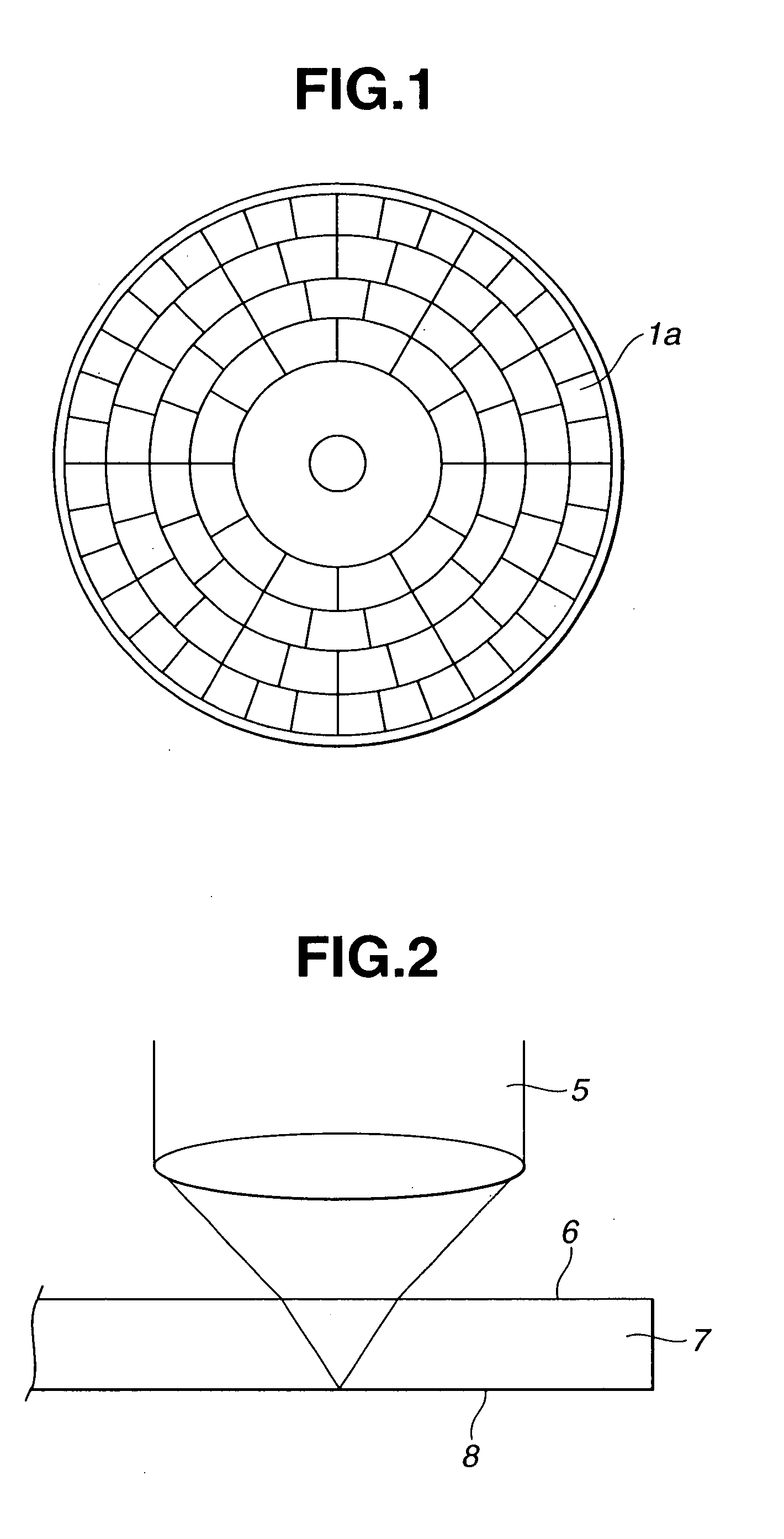
[0057]First of all, we will explain an embodiment using a magneto-optically recordable / reproducible multi-layer recording film. With a section of the used medium, as shown in FIG. 4, for example, a protective layer 10b-1, a magneto-optical recording layer 10c-1-1, 10c-1-2, 10c-1 -3, a protective layer 10d-1, and a reflective layer 10e-1 are laminated and formed one upon another by a sputtering method on a resin substrate 10a-1 having an address layout in FIG. 1.

[0058]First, a chamber for sputtering each layer was sufficiently evacuated in advance until the reached degree of vacuum is lower than 10−5 Pa. Then, in the atmosphere of 1×10⁻³ Pa to 6×10⁻³ Pa, each film was formed by a power of 2–3 kW.

[0059]As the protective layer 10b-1, a silicon nitride film of 80 nm was formed by performing reactive sputtering of a silicon target in the atmosphere of argon and nitrogen.

[0060]As the magneto-optical recording layer 10c-1-1, a film was formed to obtain 40 nm film thickn...

embodiment 2

[0087](Embodiment 2)

[0088]Next, we will explain an embodiment using a magneto-optically recordable / reproducible single-layer recording film. With a section of the used medium, as shown in FIG. 9, for example, a protective layer 10b-2, a magneto-optical recording layer 10c-2, a protective layer 10d-2, and a reflective layer 10e-2 are laminated and formed one upon another by a sputtering method on a resin substrate 10a-2 having an address layout in FIG. 1.

[0089]First, a chamber for sputtering each layer was sufficiently evacuated in advance until the reached degree of vacuum is lower than 10−5 Pa.

[0090]As the protective layer 10b-2, a silicon nitride film of 100 nm was formed by performing reactive sputtering of a silicon target in the atmosphere of argon and nitrogen.

[0091]As the magneto-optical recording layer 10c-2, a film was formed to obtain 50 nm film thickness by performing DC sputtering of a TbFeCo target in the atmosphere of argon. A composition of the target and a condition ...

embodiment 3

[0097](Embodiment 3)

[0098]Next, we will explain an embodiment using a phase-change type recording film. With a section of the used medium, as shown in FIG. 11, for example, a protective layer 10b-3, a phase-change type recording layer 10c-3, a protective layer 10d-3, and a reflective layer 10e-3 are laminated and formed one upon another by a sputtering method on a resin substrate 10a-3 having an address layout in FIG. 1.

[0099]First, a chamber for sputtering each layer is sufficiently evacuated in advance until the reached degree of vacuum is lower than 10−5 Pa.

[0100]As the protective layer 10b-3, a ZnS—SiO2 film of 130 nm was formed by performing sputtering of a ZnS—SiO2 target in the atmosphere of argon.

[0101]As the phase-change type recording layer 10c-3, a film was formed to obtain 15 nm film thickness by performing DC sputtering of a GeSbTe target in the atmosphere of argon. A composition of the target and a condition of film formation were adjusted in advance to have 500° C. cr...


PUM

PropertyMeasurementUnit
in-surface temperatureaaaaaaaaaa
temperatureaaaaaaaaaa

Abstract

When carrying out magnetization, annealing, and initialization of a recording film by applying a laser beam to the recording film while rotating an optical recording medium 10 by a motor 11, light of a strong visible-light lamp 15 is projected as parallel light to a reflecting mirror 14 via a lens 16 so as to apply light reflected by the reflecting mirror 14 to an area wider than a spot of the laser beam on the medium 10 for heating. At that time, a control unit 18 controls an intensity of the strong visible-light lamp 15 to raise a temperature of the medium 10 to a temperature of 80° C. or higher and a softening point of a substrate or lower, for example.

Description

BACKGROUND OF THE INVENTION[0001]The present invention relates to a bulk erase device for carrying out magnetization, initialization, or annealing a recording film of an optical recording medium wherein embossed-pit rows with address information are zoned in the radical direction by laser irradiation, and relates to a preheating bulk erase device for an optical recording medium, a preheating bulk erase method for an optical recording medium, and an optical recording medium, wherein the temperature of the medium is increased by partial laser irradiation to the recording film while rotating the medium.[0002]Conventionally, for optical recording media, the method called zoning is used for increasing the recording capacity by effective use of a recording area. This is a method of obtaining, on a medium rotating at constant angular velocity, for example, the recording density of a similar degree over the entire surface of the medium by switching a recording reference frequency for record...

Claims


Application Information

Patent Timeline
Patent Type & Authority Patents(United States)
IPC IPC(8): G11B11/00G11B7/0055G11B7/26G11B11/105
CPCG11B7/00557G11B11/10582G11B11/10526G11B7/268G11B11/105
Inventor NAKAYAMA, HIROSHITAKEUCHI, ATSUSHINEMOTO, JUNICHIMIURA, HIROYUKI
Owner SONY CORP
Why Eureka
Try Eureka