
Liquid circuit

a liquid circuit and circuit technology, applied in the direction of filtration separation, multi-stage water/sewage treatment, separation process, etc., can solve the problems of significant installation cost and significant danger of different lines being confused with one another, so as to save installation space, prevent damage to the components located in the liquid circuit, and facilitate assembly

Inactive Publication Date: 2007-03-20
MANN HUMMEL GMBH
View PDF13 Cites 25 Cited by
  • Summary
  • Abstract
  • Description
  • Claims
  • Application Information

AI Technical Summary

Benefits of technology

[0008]A further object of the invention is to provide a liquid circuit which is easy to understand and simple to install.
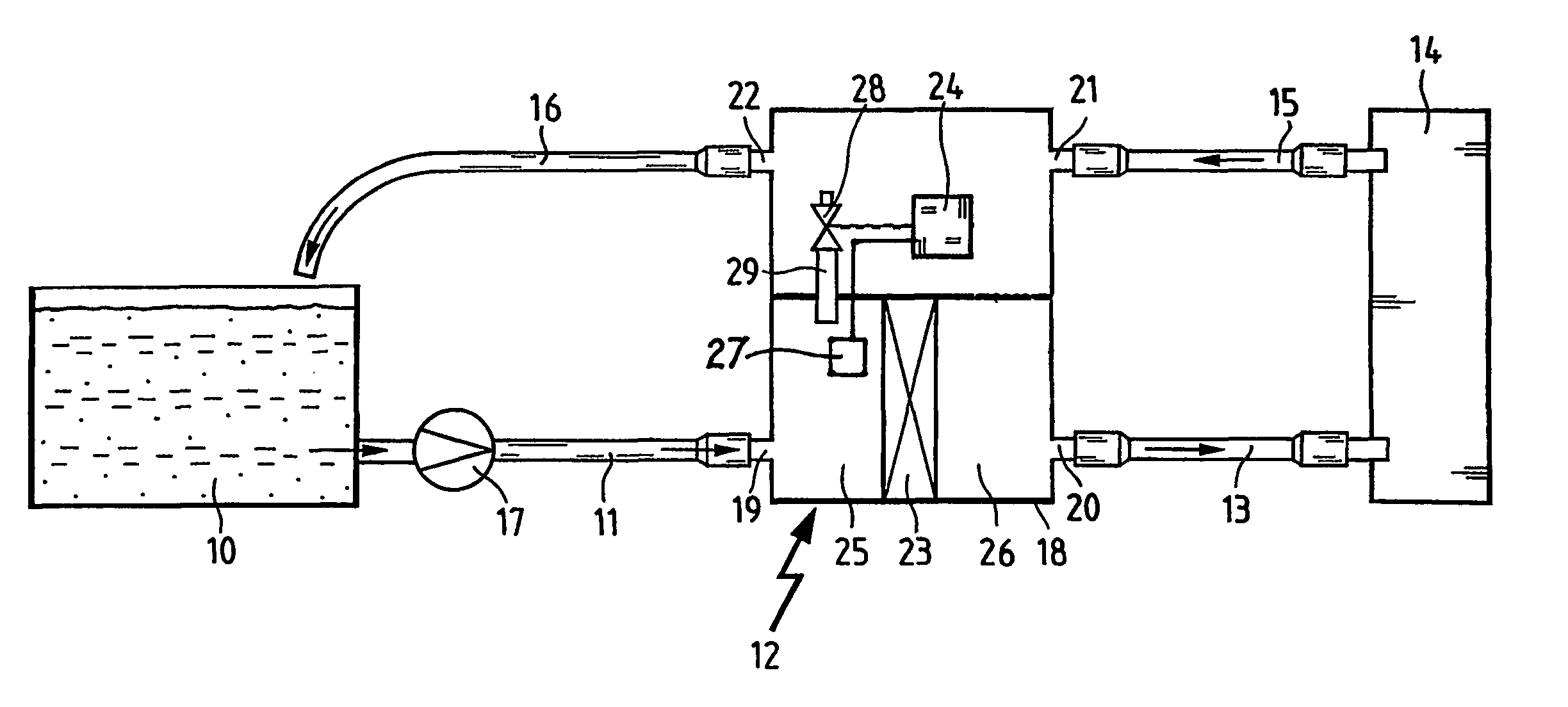
[0013]The controller comprises a temperature detection unit for determining a liquid temperature existing in the liquid, and a valve, which is controllable in accordance with the liquid temperature. The liquid temperature may be detected before or after the filter element. As soon as the liquid temperature is above a defined temperature, the controller conducts the liquid back into the liquid storage vessel via a liquid drain line which is connected to a liquid outlet fixed on the housing. If the liquid temperature is below the defined temperature, the liquid not accepted by the user device is returned from the controller to the filter element via a connection line. In this way, the unfiltered liquid is mixed with the returned liquid, which has a higher liquid temperature, through which the viscosity of the liquid to be filtered is reduced. Consequently, the resistance to flow produced by the filter element may be decreased.
[0016]Another possible liquid consuming device be, for example, the transmission of an internal combustion engine, which is connected to an oil circuit. The oil circuit is a closed system, in which the oil is used to reduce the material wear. The colder the oil is, the more viscous it is. This is particularly disadvantageous during cold starting of an engine, since in this case the lubricant film may be interrupted and therefore significant wear may occur. By mixing the cold oil from the liquid tank with the heated returned oil, the viscosity of the oil may be reduced and the lubrication in the cold state may be improved.
[0020]It is advantageous to position a ventilation device in the liquid filter system, through which gases may be separated. This ventilation device may be designed, for example, as a leakage line or as a pressure-dependent valve. If the ventilation device is constructed as a valve, it may open automatically above a predetermined pressure and allow the gas to escape. The ventilation device is preferably positioned before the filter element, since gases accumulate at this point.
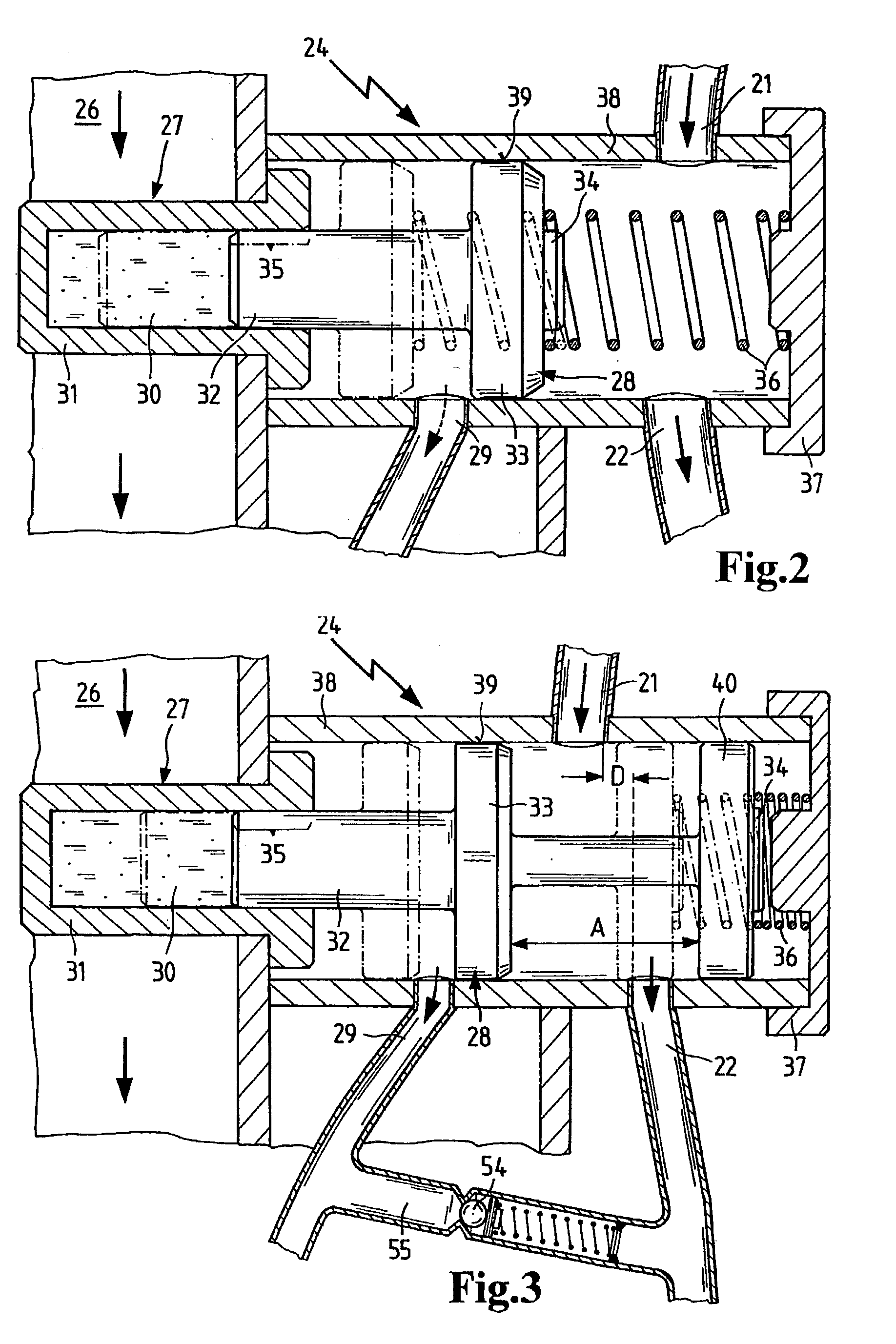
[0024]A further embodiment of the present invention includes a non-return valve or check valve, positioned downstream from the controller, which may be formed, for example, by a shield valve. This check valve prevents uncontrolled emptying of the liquid filter system and is preferably positioned between the controller and the liquid drain line. In other check valve configurations, the valve may be integrated in the liquid drain line, as a result of which the liquid is not able to drain into the liquid storage vessel.
[0025]In accordance with a further embodiment of the present invention, a pressure relief or overpressure valve, which is preferably positioned downstream from the controller, is integrated into the liquid filter system. The overpressure valve is designed in such a way that in the event of excessive liquid pressure in the liquid circuit, at least a part of the liquid may drain into the liquid storage vessel, so that damage to the components located in the liquid circuit may be prevented. This overpressure valve may be positioned between the controller and the liquid drain line. In an alternative embodiment, the overpressure valve may be integrated into the liquid outlet. Furthermore, the overpressure valve and the check valve may be combined into a single component, so that assembly is made easier and installation space is saved.

Problems solved by technology

However, the fuel injection system includes a large number of lines, connected by valves and thermostats to a central processing unit.
In this case, during the installation of the fuel injection system on an internal combustion engine, there is a significant outlay for installation and there is also a significant danger that different lines may be confused with one another.

Method used


Image

  • Liquid circuit
  • Liquid circuit
  • Liquid circuit

Examples


Embodiment Construction

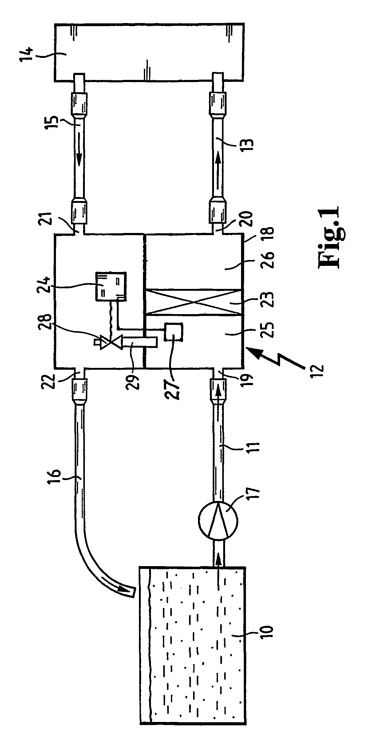
[0035]A liquid circuit is schematically illustrated in FIG. 1. The liquid circuit is formed by a liquid storage vessel 10, an unfiltered liquid line 11, extending from the liquid storage vessel 10, a liquid filter system 12 attached to the unfiltered liquid line 11, a filtered liquid line 13 which connects a device 14 which consumes or uses the liquid to the liquid filter system 12, a liquid return line 15, and a liquid drain line 16. In order that a liquid may circulate in the liquid circuit, a liquid pump 17 is provided, which generates a liquid pressure in the liquid circuit and has a larger delivery volume than the maximum consumption of the user device 14.

[0036]In this illustrative embodiment, the liquid pump 17 is positioned in the unfiltered liquid line. However, the positioning of the liquid pump 17 within the liquid circuit is arbitrary. Consequently, if desired, pump 17 could be positioned, for example, in the liquid storage vessel, in the liquid filter system, or in other...


PUM

PropertyMeasurementUnit
temperatureaaaaaaaaaa
temperaturesaaaaaaaaaa
pressureaaaaaaaaaa

Abstract

A circuit for filtering a liquid, comprising a storage vessel (10), a pump (17), a consumer device (14), a filter element (23) and a controller (24). The circuit maybe used in systems where liquid, e.g. water, oil or fuel, is filtered and at least part thereof is returned to the storage vessel. Liquid is pumped in the circuit from the storage vessel by the pump through lines (11, 13, 15, 16), filtered by filter (23) and supplied to the consumer device. Excess liquid not required by the consumer device (14) is returned via return line (15) to the controller (24) which directs the liquid either to the filter or the storage vessel—depending on liquid temperature. The controller (24) and the filter are arranged in a common housing (18) having connectors for an unfiltered liquid inlet (19), a filtered liquid outlet (20), a liquid return (21) and a liquid outlet (22). The connectors (19–22) enable rapid assembly of the circuit.

Description

CROSS REFERENCE TO RELATED APPLICATIONS[0001]This application is a continuation of international patent application no. PCT / EP01 / 06548, filed Jun. 9, 2001, designating the United States of America and published in German as WO 02 / 01061, the entire disclosure of which is incorporated herein by reference. Priority is claimed based on Federal Republic of Germany patent application no. DE 100 30 324.2, filed Jun. 27, 2000.BACKGROUND OF THE INVENTION[0002]The present invention relates to a liquid circuit comprising a liquid storage vessel, a liquid pump, a device which consumes or utilizes the liquid, a filter element having an unfiltered liquid side and a filtered liquid side, and a controller for returning excess liquid not needed by the consumer device at least partially to the filter element.[0003]German Patent No. DE 197 14 488 discloses a method and a fuel injection system for heating a fuel. In the method of heating fuel, the fuel is compressed by a fuel pump to an injection press...

Claims


Application Information

Patent Timeline
Patent Type & Authority Patents(United States)
IPC IPC(8): B01D35/14F02M37/22B01D29/60B01D35/147B01D36/00F02D33/00F02M37/00F02M37/28F02M37/30F02M37/48F02M37/54
CPCB01D29/608B01D35/147B01D35/1573B01D35/1576B01D36/003F02D33/006F02M37/0035F02M37/0052F02M37/22B01D35/157B01D35/18F02M2037/226F02M37/223B01D2201/46F02M37/221F02M37/46F02M37/30F02M37/54F02M37/28F02M37/48
Inventor ROESGEN, ANDRE
Owner MANN HUMMEL GMBH
Learn More