
Method and apparatus for transmitting and receiving data to and from a downhole tool

Active Publication Date: 2007-03-13
INTELLISERV
View PDF120 Cites 51 Cited by
  • Summary
  • Abstract
  • Description
  • Claims
  • Application Information

AI Technical Summary

Benefits of technology

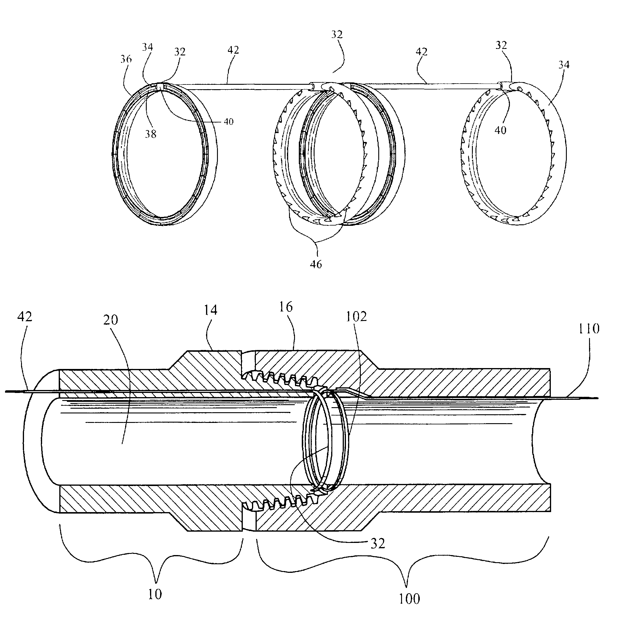
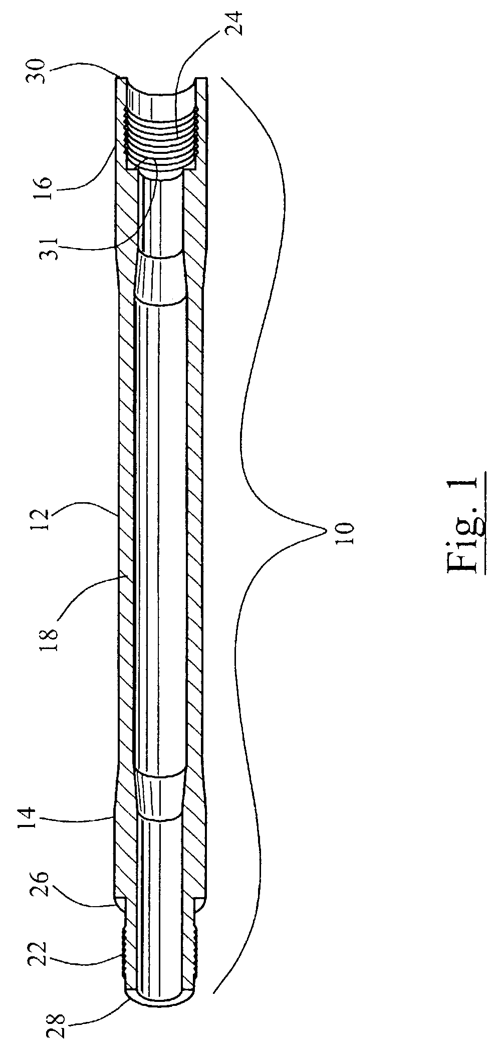
[0008]Disclosed is a downhole transmission line network that may be easily implemented and used in connection with new or preexisting downhole tools that are not configured to convey signals along their lengths without requiring substantial modification of such tools and without compromising their structural integrity.
[0009]Also disclosed is a downhole transmission line network that effectively resists the extreme temperatures, pressure, torque, and corrosive environment characteristic of a downhole well.
[0010]Also disclosed is a downhole transmission line network system that accurately and reliably transmits and receives signals between discrete downhole tools while permitting slight physical gaps between such downhole tools.
[0011]Furthermore, a downhole transmission line network system is disclosed that transmits and receives signals between discrete downhole tools with a high degree of accuracy so as to minimize the need for repeaters.

Problems solved by technology

Several attempts have been made to devise a successful system for accessing such drill string data; as of yet, however, the goal has been. unrealized.
One of the obstacles to realizing the goal of real time communication along a drill string is the wide variety of tools required for drilling a modern day well that a downhole transmission network must accommodate.
Although at first glance many downhole tools seem to resemble one another, the industry thus far has been unable to develop a transmission network capable of accommodating variations between tools without compromising their structural integrity or requiring their special manufacture.
This problem is exacerbated by certain downhole tools that require unique internal components to achieve unique functions related to drill exploration and excavation.

Method used


Image

  • Method and apparatus for transmitting and receiving data to and from a downhole tool
  • Method and apparatus for transmitting and receiving data to and from a downhole tool
  • Method and apparatus for transmitting and receiving data to and from a downhole tool

Examples


Embodiment Construction

[0024]The present invention may be embodied in other specific forms without departing from its spirit or essential characteristics. The described embodiments are to be considered in all respects only as illustrative and not restrictive. The scope of the invention is, therefore, indicated by the appended claims rather than by the foregoing description. All changes that come within the meaning and range of equivalency of the claims are to be embraced within their scope.

[0025]As used in this specification, the term “downhole” is intended to have a relatively broad meaning, including such environments as drilling for oil and / or gas, and extraction of other subterranean minerals, as well as for drilling for water and other subsurface liquids, and for geothermal exploration. Also included are systems of casings and other equipment used in the production of these sub-surface resources. The term “downhole tool” or “tool” refers to any pipe or tool having a central bore and used in explorati...


PUM


Abstract

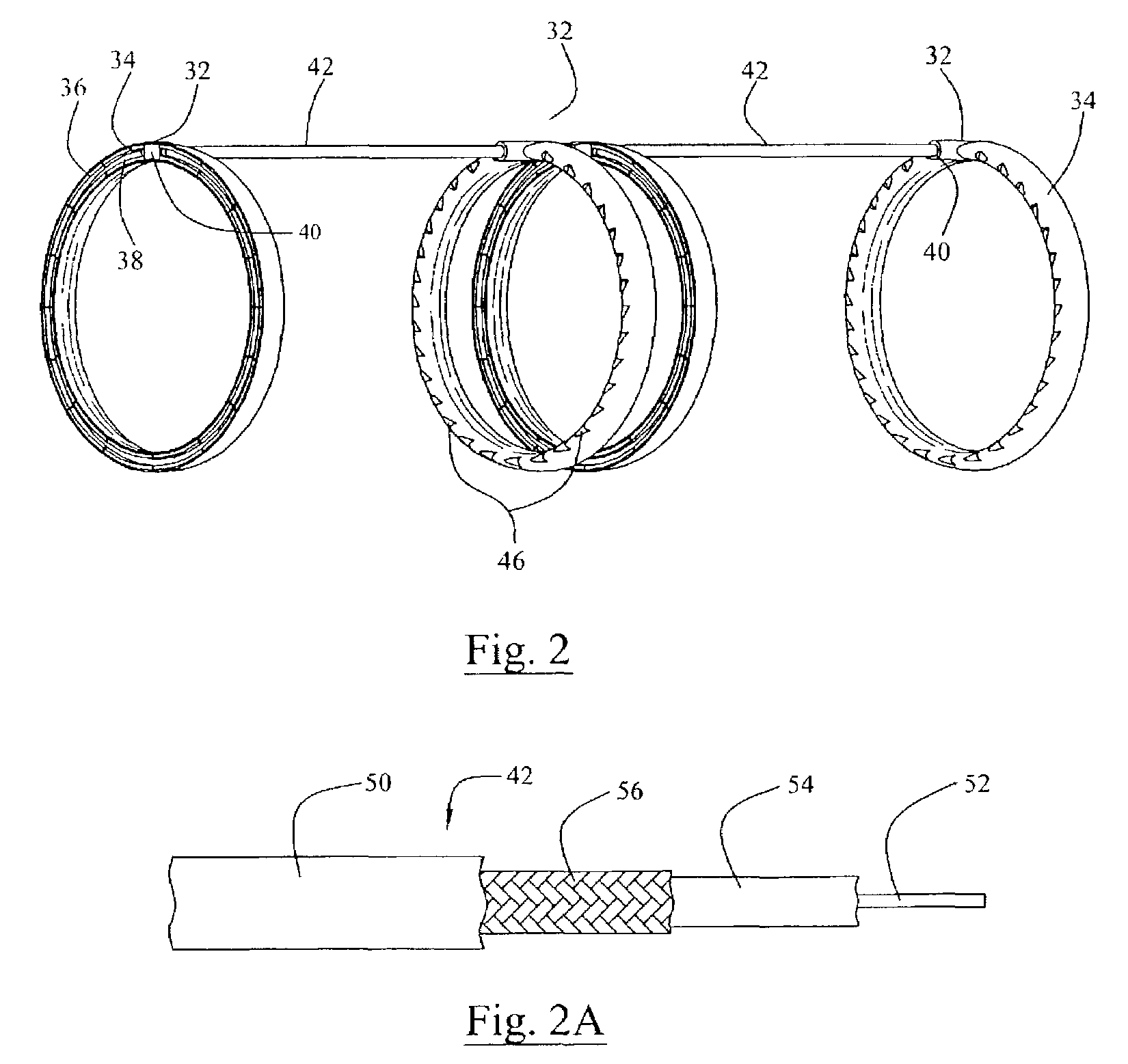
A transmission line network system for transmitting and / or receiving data from a downhole tool. The invention is achieved by providing one or more transceiving elements, preferably rings, at either end of a downhole tool. A conduit containing a coaxial cable capable of communicating an electrical signal is attached to the transceiving element and extends through a central bore of the downhole tool and through the central bore of any tool intermediate the first transceiving element and a second transceiving element. Upon receiving an electrical signal from the cable, the second transceiving element may convert such signal to a magnetic field. The magnetic field may be detected by a third transceiving element in close proximity to the second transceiving element. In this manner, many different tools may be included in a downhole transmission network without requiring substantial modification, if any, of any particular tool.

Description

CROSS REFERENCE TO RELATED APPLICATIONS[0001]The present patent application claims the benefit of the filing date of the U.S. patent application to David R. Hall, et al., filed Feb. 3, 2003, entitled “Data Transmission System for a Downhole Component,” which claims priority to U.S. Provisional Patent Application Ser. No. 60 / 444,100 to David R. Hall, et al., filed Jan. 31, 2003, also entitled “Data Transmission System for a Downhole Component,”both of which are hereby incorporated in their entireties by reference.FEDERAL RESEARCH STATEMENT[0002]This invention was made with government support under Contract No. DE-FC26 01NT41229 awarded by the U.S. Department of Energy. The government has certain rights in the invention.BACKGROUND OF INVENTION[0003]The present invention relates to the field of data transmission systems for downhole environments, such as along a drill string used in oil and gas exploration or along casings or other equipment used in oil and gas production. More particu...

Claims


Application Information

Patent Timeline
IPC IPC(8): E21B47/16E21B17/00E21B17/02E21B47/12F16L15/00H01F38/14H01R9/05H01R13/523H01R13/646H01R13/66
CPCE21B17/003E21B17/028E21B47/122F16L15/003F16L15/009H01R13/523H01R13/6633H01R24/566H01F38/14H01R2103/00H01F2038/143H01R9/05E21B47/13E21B17/0285E21B17/0283
Inventor HALLFOX, JOE
Owner INTELLISERV
Learn More