
Method and system for using an image based autofocus algorithm

an image and autofocus technology, applied in the field of image based autofocus optimization, can solve the problems of not adequately compensating for the curvature of the earth, and range estimation systems also not well suited to rough terrain. , to achieve the effect of increasing the robustness of the focus measur

Inactive Publication Date: 2007-03-06
LOCKHEED MARTIN CORP
View PDF3 Cites 28 Cited by
  • Summary
  • Abstract
  • Description
  • Claims
  • Application Information

AI Technical Summary

Benefits of technology

[0013]In another exemplary embodiment, an image based autofocus method includes: receiving image data; applying a 3×3 filter to a region of data; applying a 5×5 filter to a region of data; and using the 3×3 filtered data and the 5×5 filtered data to calculate a focus measure. The method repeats the determination of the focus measure calculation for the neighboring pixels of an individual pixel. The invention calculates a difference in focus measure from pixel to pixel in an observation area to determine a focus measure for that frame of data. In one exemplary embodiment, the observation area can include a 64×64 pixel region. One increases the robustness of the focus measure obtained from a frame of data by using multiple regions of interest (ROI) and the ROI can be selected from a center location of a field of view and the ROI is also selected from a center location of an object being tracked.

Problems solved by technology

These conventional systems have several disadvantages associated with their practical application.
One problem is that the factory calibrated athermalization may drift significantly and change over time from the original calibration setpoint that was established in the factory.
Another problem is that range estimation for many of these systems is based on flat earth approximations, which do not adequately compensate for the earth's curvature.
These range estimation systems also do not compensate well for rough terrain, such as that containing hills, mountains and other topographic barriers.
Therefore, these flat earth approximations are not always valid and tend to introduce inaccuracies into the system which in turn adversely impact the accuracy of systems that rely on these techniques.

Method used


Image

  • Method and system for using an image based autofocus algorithm
  • Method and system for using an image based autofocus algorithm
  • Method and system for using an image based autofocus algorithm

Examples


Embodiment Construction

[0024]Aspects of the invention are disclosed in the accompanying description. Alternate embodiments may be devised without departing from the spirit or the scope of the present invention.

[0025]An image based autofocus method utilizes the concept of keeping a sensor or device that is receiving image data in focus based upon scene information residing in an acquired image set of data.

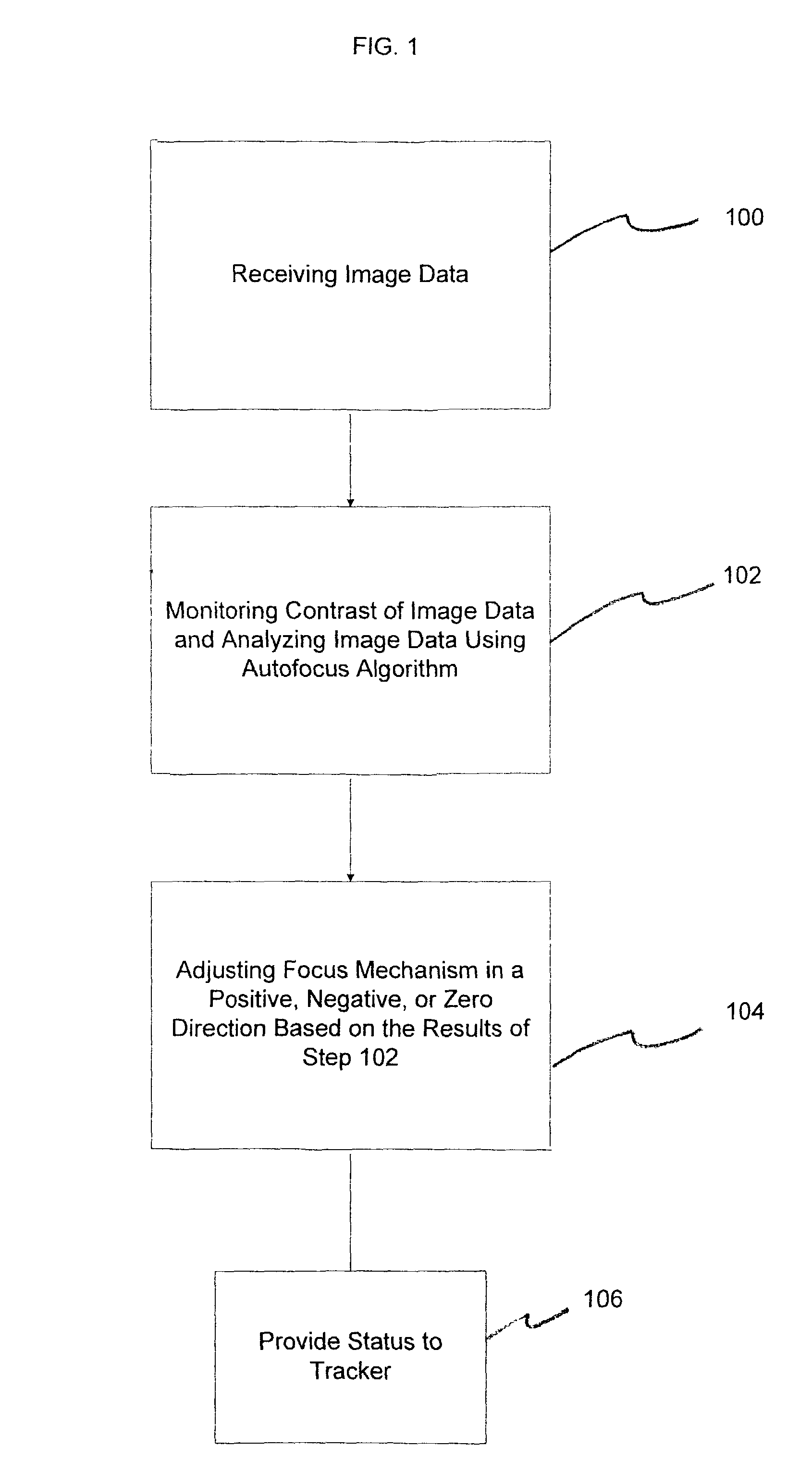
[0026]FIG. 1 illustrates a block diagram representation of an exemplary method implementing the present invention. In step 100, image data is received by a sensor or some other type of receiving device (such as an optical seeker head on a guided missile).

[0027]In step 102, the contrast existing among the received image data is monitored and analyzed. One way of monitoring the contrast among the image data is to perform the monitoring and analyzing operation of image data at the pixel level and contrast and compare the different pixels with each other in an image kernel(s). One exemplary way of accomplishi...


PUM


Abstract

An image based autofocus method and system that includes receiving image data; monitoring and analyzing the contrast between different portions of the image data in determining the location of a target wherein the different portions of the image data contain at least one type of image pixel information and the monitoring and analyzing are performed using at least one kernel filter to determine a focus measure; adjusting a focus mechanism that is focusing on the image data; observing an image quality of the image data that has been focused; and continuously outputting an image to support an image processing frame rate and adjusting the focus mechanism to obtain an improved focus image by adjusting the focus mechanism in a positive direction, a negative direction or a zero (0) direction based upon effectuating a desired change in the observed image quality of the image data.

Description

FIELD OF THE INVENTION[0001]The present invention relates to a method and system for optimizing the focusing of an image using an autofocus algorithm. More particularly, the algorithm is used to optimize the focus of the optics and optical systems relating to targeting systems for missiles that are seeking to acquire and lock onto a prospective target against a surrounding image background.BACKGROUND OF THE INVENTION[0002]In many targeting and missile guidance systems, optical based seekers are used to acquire, track and engage a prospective target. In the course of using these optical systems, the system is often required to focus on an image that is residing in a set of received imagery thought to contain a target. In accomplishing this objective, imaging systems of the present day are becoming more and more automatic in their ability to focus and lock onto a target.[0003]Many advanced imaging systems have some type of autofocus capability. One autofocus technique is to measure or...

Claims


Application Information

Patent Timeline
IPC IPC(8): G03B13/36H04N5/232
CPCH04N5/23212H04N23/673
Inventor ALDERSON, TIMOTHY
Owner LOCKHEED MARTIN CORP
Learn More