
Inductance device

a technology of inductance and ring core, which is applied in the direction of inductance, inductance with magnetic core, inductance/yokes, etc., can solve the problems of increasing the number of parts, difficult to accurately position drum core and ring core, and inability to obtain predetermined inductance values, etc., to achieve excellent productivity, reduce the effect of mechanical shocks and strong resistance to mechanical shocks

Inactive Publication Date: 2007-02-27
SUMIDA TECH +1
View PDF20 Cites 18 Cited by
  • Summary
  • Abstract
  • Description
  • Claims
  • Application Information

AI Technical Summary

Benefits of technology

[0016]In view of such circumstances, it is an object of the present invention to provide an inductance device which is excellent in productivity and strong against mechanical shocks, and can be made smaller, while being able to suppress magnetic saturation and prevent magnetic fluxes from leaking from around a wound wire.

Problems solved by technology

This is because of the fact that both of the drum core and ring core formed from ferrite have a high permeability, so that magnetic saturation will occur if the clearance therebetween is too small, whereby a predetermined inductance value may not be obtained.
Since the ring core incurs a dimensional tolerance during the making thereof, it is quite difficult for the drum core and ring core to be positioned accurately when concentrically attaching and securing the ring core to the outer periphery of the drum core.
However, since the flange (upper flange) of the drum core farther from the terminal board mounting the drum core is bonded to the upper end of the ring core by an adhesive, while an assembling operation is carried out using a holder for holding the drum core and ring core, the high-frequency transformer disclosed in reference 1 may be problematic in that the number of parts increases while the manufacturing process is complicated.
Since the technique disclosed in reference 2 requires an operation of winding a tape-like magnetic member about the drum core while extending it between the upper flange and lower flange thereof, the assembling operation is not easy in a minute inductance device whose upper flange and lower flange have a gap of about several millimeters or less therebetween in particular.
Further, the techniques disclosed in references 1 to 3 are susceptible to mechanical shocks such as falling and punching.
Namely, whether drum cores or ring cores, magnetic cores used in inductance devices in general are formed by baking ferrite or the like and thus are susceptible to mechanical shocks such as falling and punching and are likely to be damaged though exhibiting a hardness to some extent.

Method used


Image

  • Inductance device
  • Inductance device
  • Inductance device

Examples


Embodiment Construction

[0028]In the following, the inductance device in accordance with an embodiment of the present invention will be explained with reference to drawings.

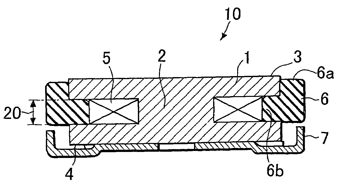
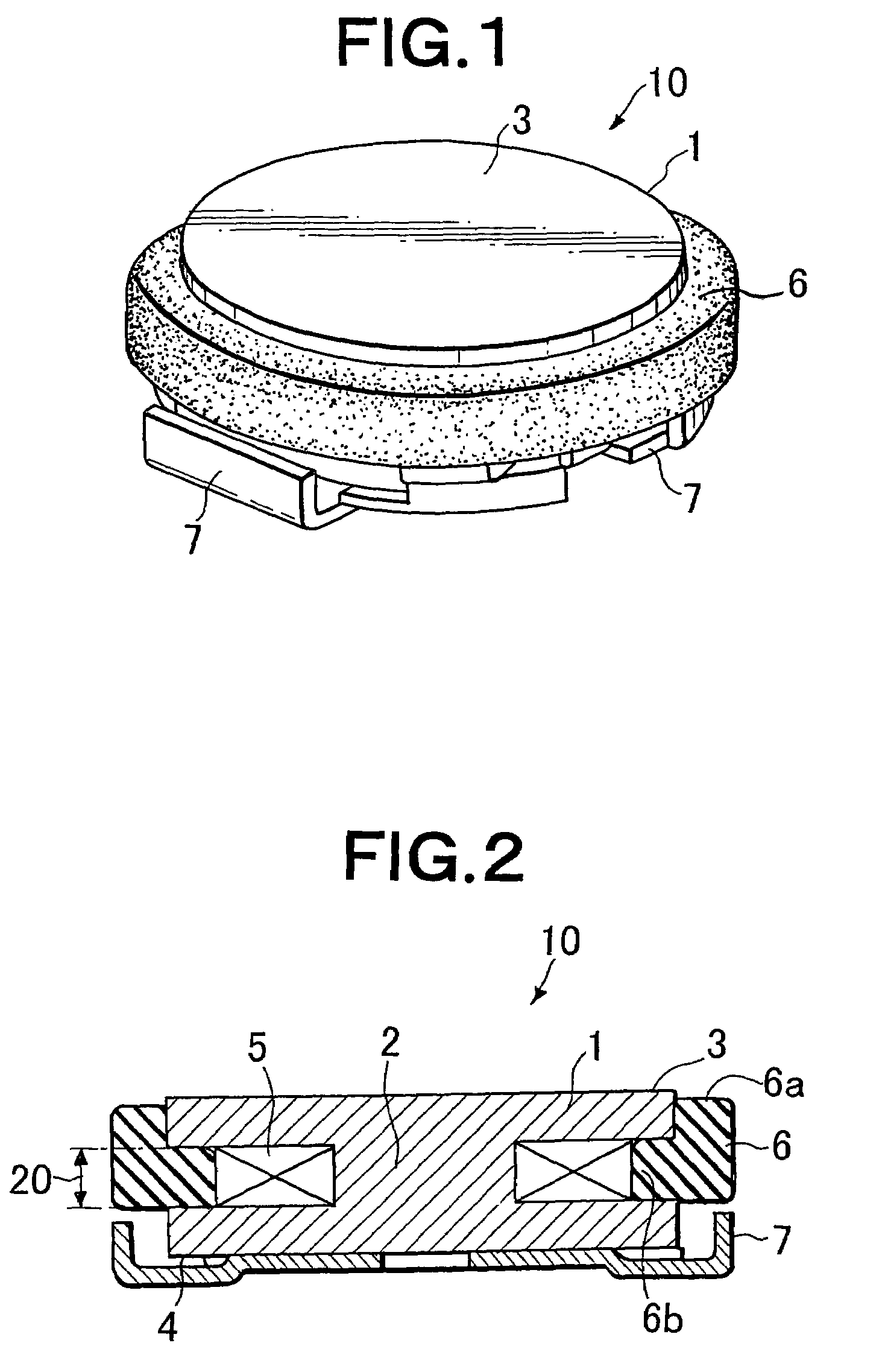
[0029]FIG. 1 is a perspective view showing the exterior of the inductance device in accordance with the embodiment, whereas FIG. 2 is a vertical sectional view thereof.

[0030]This inductance device 10 comprises a drum core 1 in which a center core 2 and flanges 3, 4 are integrally formed from ferrite.

[0031]The center core 2 of the drum core 1 is wound with a wire 5, whereas a magnetic gap 20 is formed between the upper flange 3 and lower flange 4. A terminal 7 for external wiring connection is provided at the outer surface of the bottom part of the lower flange 4. The drum core 1 may be mounted and secured onto a base substrate (not depicted) provided with the terminal 7.

[0032]For example, the individual parts of the inductance device 10 have such dimensions that the diameter of each of the upper flange 3 and lower flange 4 is 2.8 mm, th...


PUM

PropertyMeasurementUnit
total weightaaaaaaaaaa

Abstract

An inductance device comprises a drum core having a center core, and flanges integrated therewith. The center core is wound with a wire, whereas a magnetic gap is formed between the upper flange and lower flange. The magnetic gap is closed with an insulator, mixed with a magnetic substance, having rubber elasticity. The insulator comprises an overhang and an insertion integrally formed therewith. The overhang presses a region in the upper flange so as to hang from this region. The insertion tightly fits into the magnetic gap.

Description

RELATED APPLICATIONS[0001]This application claims the priority of Japanese Patent Application No. 2003-92759 filed on Mar. 28, 2003, which is incorporated herein by reference. This application is a continuation of U.S. patent application Ser. No. 10 / 682,487, which is also incorporated by reference.BACKGROUND OF THE INVENTION[0002]1. Field of the Invention[0003]The present invention relates to an inductance device suitable for electronic instruments required to be made smaller in particular, such as mobile phones, digital cameras, mobile instruments, and notebook PCs.[0004]2. Description of the Prior Art[0005]Known as this kind of inductance device is one using a drum core made of ferrite, in which a ring core made of ferrite concentrically covers the outer periphery of a magnetic gap existing between its upper flange and lower flange, so as to prevent magnetic fluxes from leaking from the gap, and increase permeability.[0006]It is necessary for thus configured inductance device to h...

Claims


Application Information

Patent Timeline
Patent Type & Authority Patents(United States)
IPC IPC(8): H01F27/02H01F17/00H01F3/10H01F3/12H01F3/14H01F17/04H01F27/29H01F27/33H01F27/36
CPCH01F17/045H01F3/10H01F3/12H01F3/14H01F2017/048H01F27/292H01F27/33H01F27/365H01F27/022H01F27/36H01F27/366H01F17/00
Inventor OOKI, JUICHI
Owner SUMIDA TECH
Learn More