
Methods for targeted electrosurgery on contained herniated discs

a technology of electrosurgery and discs, applied in the field of medical devices, can solve the problems of disc shock absorption, pain and sensory and motor deficit, back and leg pain, etc., and achieve the effects of reducing the pressure on the annulus fibrosus, reducing the pressure on the affected nerve root, and alleviating neck and back pain

Inactive Publication Date: 2007-02-20
ARTHROCARE
View PDF236 Cites 612 Cited by
  • Summary
  • Abstract
  • Description
  • Claims
  • Application Information

AI Technical Summary

Benefits of technology

[0017]In one aspect, the present invention provides a method of treating a herniated intervertebral disc. The method comprises positioning at least one active electrode within the intervertebral disc. High frequency voltage is applied between the active electrode(s) and one or more return electrode(s) to debulk, ablate, coagulate, and / or shrink at least a portion of the nucleus pulposus and / or annulus. In one embodiment, the high frequency voltage is selected to ablate tissue within the nucleus. In other embodiments, the high frequency voltage is selected to effect a controlled depth of thermal heating to reduce the water content of the nucleus pulposus, thereby debulking the nucleus pulposus and reducing the internal pressure on the annulus fibrosus.
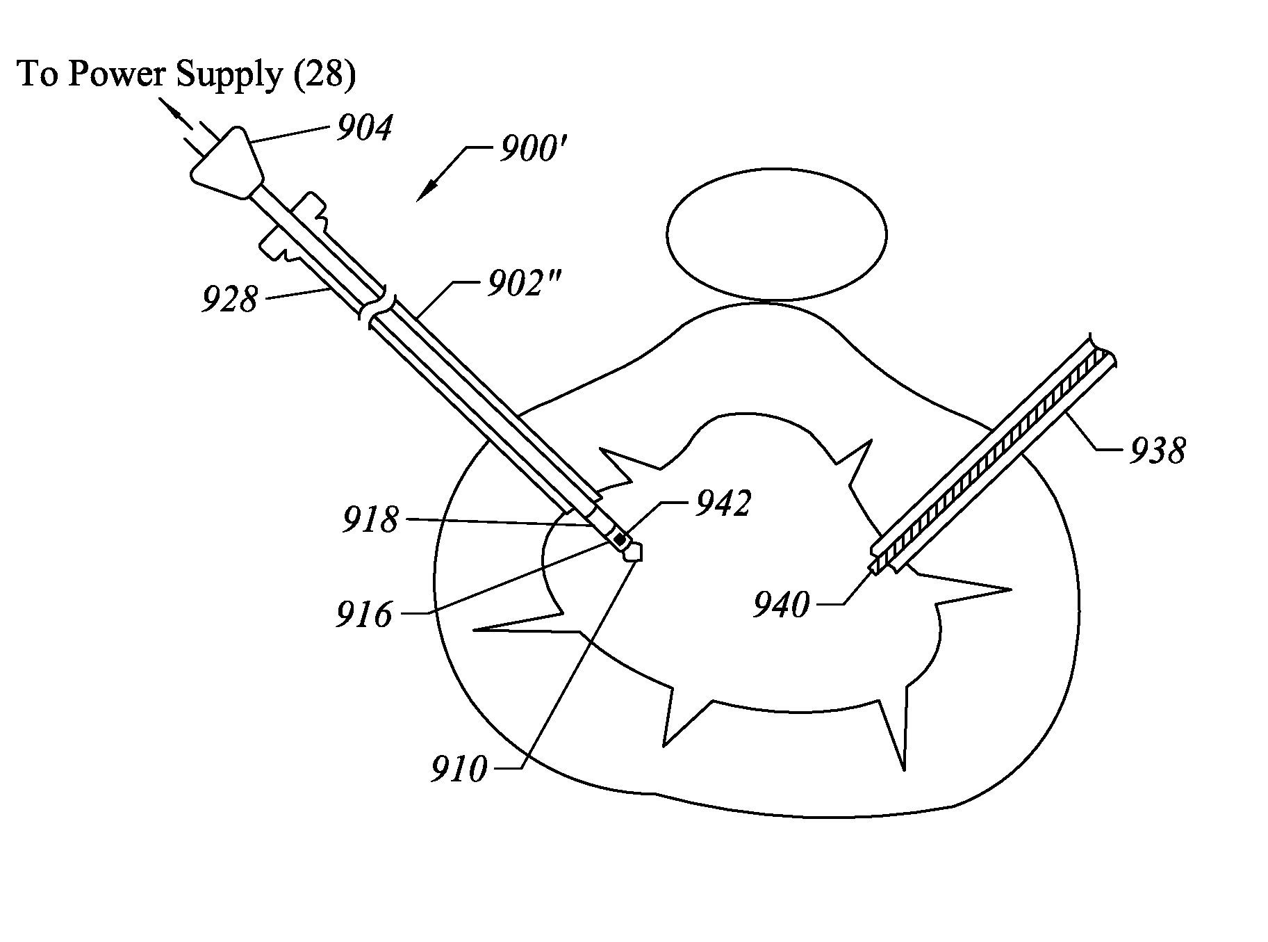
[0019]In another aspect, the present invention provides a method of treating a disc having a contained herniation or fissure. The method comprises introducing an electrosurgical instrument into the patient's intervertebral disc either percutaneously or through an open procedure. The instrument is steered or otherwise guided into close proximity to the contained herniation or fissure and a high frequency voltage is applied between an active electrode and a return electrode so as to debulk the nucleus pulposus adjacent the contained herniation or fissure. In some embodiments a conductive fluid is delivered into the intervertebral disc prior to applying the high frequency voltage to ensure that sufficient conductive fluid exists for plasma formation and to conduct electric current between the active and return electrodes. Alternatively, the conductive fluid can be delivered to the target site during the procedure. The heating delivered through the electrically conductive fluid debulks the nucleus pulposus, and reduces the pressure on the annulus fibrosus so as to reduce the pressure on the affected nerve root and alleviate neck and back pain.
[0022]The active electrode(s) may comprise a single active electrode, or an electrode array, extending from an electrically insulating support member, typically made of an inorganic material such as a ceramic, a silicone or a glass. The active electrode will usually have a smaller exposed surface area than the return such that the current densities are much higher at the active electrode than at the return electrode. Preferably, the return electrode has a relatively large, smooth surfaces extending around the instrument shaft to reduce current densities, thereby minimizing damage to adjacent tissue.
[0025]By applying a high frequency voltage between the at least one active electrode and at least one return electrode, disc tissue in the vicinity of the contained herniation undergoes molecular dissociation. In one embodiment, the at least one active electrode includes an electrode head having an apical spike and a cusp, wherein the electrode head is adapted for providing a high current density in the vicinity of the electrode head when the high frequency voltage is applied between the at least one active electrode and the return electrode. The method may be conveniently performed percutaneously, and one or more stages in the treatment or procedure may be performed under fluoroscopy to allow visualization of the shaft within the disc to be treated.

Problems solved by technology

This results in a weakening of the shock absorption properties of the disc and a narrowing of the nerve openings in the sides of the spine which may pinch these nerves.
This disc degeneration can eventually cause back and leg pain.
A weakening of the annulus fibrosus can cause the disc to bulge, e.g., a contained herniation, and the mere proximity of the nucleus pulposus or the damaged annulus to a nerve can cause direct pressure against the nerve, resulting in pain and sensory and motor deficit.
In some cases, the disc tissue is irreparably damaged, thereby necessitating removal of a portion of the disc or the entire disc to eliminate the source of inflammation and pressure.
In addition, the risk of instability from ligament and bone removal is generally lower in endoscopic procedures than with open procedure.
Unfortunately, these mechanical instruments greatly lengthen and increase the complexity of the procedure.
In addition, these instruments might sever blood vessels within this tissue, usually causing profuse bleeding that obstructs the surgeon's view of the target site.
In addition to the above problems with mechanical instruments, there are serious concerns because these instruments are not precise, and it is often difficult, during the procedure, to differentiate between the target disc tissue, and other structures within the spine, such as bone, cartilage, ligaments, nerves and non-target tissue.
Unfortunately, lasers are both expensive and somewhat tedious to use in these procedures.
Another disadvantage with lasers is the difficulty in judging the depth of tissue ablation.
Monopolar devices, however, suffer from the disadvantage that the electric current will flow through undefined paths in the patient's body, thereby increasing the risk of undesirable electrical stimulation to portions of the patient's body.
This current, however, may inadvertently flow along body paths having less impedance than the defined electrical path, which will substantially increase the current flowing through these paths, possibly causing damage to or destroying surrounding tissue or neighboring peripheral nerves.
Other disadvantages of conventional RF devices, particularly monopolar devices, is nerve stimulation and interference with nerve monitoring equipment in the operating room.
In addition, these devices typically operate by creating a voltage difference between the active electrode and the target tissue, causing an electrical arc to form across the physical gap between the electrode and tissue.
At the point of contact of the electric arcs with tissue, rapid tissue heating occurs due to high current density between the electrode and tissue.
Thus, the tissue is parted along the pathway of evaporated cellular fluid, inducing undesirable collateral tissue damage in regions surrounding the target tissue site.
This collateral tissue damage often causes indiscriminate destruction of tissue, resulting in the loss of the proper function of the tissue.
In addition, the device does not remove any tissue directly, but rather depends on destroying a zone of tissue and allowing the body to eventually remove the destroyed tissue.
Contained herniation often causes pain due to nerve root compression resulting from protrusion of the nucleus pulposus into the annulus fibrosus and concomitant bulging of the annulus fibrosus at the disc perimeter.

Method used


Image

  • Methods for targeted electrosurgery on contained herniated discs
  • Methods for targeted electrosurgery on contained herniated discs
  • Methods for targeted electrosurgery on contained herniated discs

Examples


Embodiment Construction

[0072]The present invention provides systems and methods for selectively applying electrical energy to a target location within or on a patient's body, particularly including support tissue or other body structures in the spine. These procedures include treating interspinous tissue, degenerative discs, laminectomy / discectomy procedures for treating herniated discs, decompressive laminectomy for stenosis in the lumbosacral and cervical spine, localized tears or fissures in the annulus, nucleotomy, disc fusion procedures, medial facetectomy, posterior lumbosacral and cervical spine fusions, treatment of scoliosis associated with vertebral disease, foraminotomies to remove the roof of the intervertebral foramina to relieve nerve root compression and anterior cervical and lumbar discectomies. These procedures may be performed through open procedures, or using minimally invasive techniques, such as thoracoscopy, arthroscopy, laparascopy or the like.

[0073]The present invention involves te...


PUM

PropertyMeasurementUnit
Temperatureaaaaaaaaaa
Angleaaaaaaaaaa

Abstract

Apparatus and methods for treating an intervertebral disc by ablation of disc tissue. A method of the invention includes positioning at least one active electrode within the intervertebral disc, and applying at least a first high frequency voltage between the active electrode(s) and one or more return electrode(s), wherein the volume of the nucleus pulposus is decreased, pressure exerted by the nucleus pulposus on the annulus fibrosus is reduced, and discogenic pain of a patient is alleviated. In other embodiments, a curved or steerable probe is guided to a specific target site within a disc to be treated, and the disc tissue at the target site is ablated by application of at least a first high frequency voltage between the active electrode(s) and one or more return electrode(s). A method of making an electrosurgical probe is also disclosed.

Description

CROSS-REFERENCES TO RELATED APPLICATIONS[0001]The present application is a continuation-in-part of U.S. patent application Ser. No. 09 / 316,472, filed May 21, 1999 (now U.S. Pat. No. 6,264,650), which is a continuation-in-part of U.S. patent application Ser. No. 09 / 295,687, filed Apr. 21, 1999 (now U.S. Pat. No. 6,203,542) and U.S. patent application Ser. No. 09 / 054,323 (now U.S. Pat. No. 6,063,079) and Ser. No. 09 / 268,616, (now U.S. Pat. No. 6,159,208), filed Apr. 2, 1998 and Mar. 15, 1999, respectively, each of which are continuation-in-parts of U.S. patent application Ser. No. 08 / 990,374, filed Dec. 15, 1997 (now U.S. Pat. No. 6,109,268), which is a continuation-in-part of U.S. patent application Ser. No. 08 / 485,219, filed on Jun. 7, 1995 (now U.S. Pat. No. 5,697,281), the complete disclosures of which are incorporated herein by reference for all purposes. The present application is also a continuation-in-part of U.S. patent application Ser. No. 09 / 026,851, filed Feb. 20, 1999 (no...

Claims


Application Information

Patent Timeline
IPC IPC(8): A61B18/14A61B17/56A61B17/00A61B18/00A61B18/12A61B19/00A61F2/02A61M1/00A61M3/02
CPCA61B18/148A61B18/1482A61B18/1485A61B18/149A61B18/1492A61B1/3135A61F2/2493A61B18/1206A61B18/14A61B18/1477A61B19/201A61B2017/00026A61B2017/00084A61B2017/00101A61B2017/00247A61B2017/00261A61B2017/00274A61B2018/00029A61B2018/00083A61B2018/00119A61B2018/0016A61B2018/00178A61B2018/00327A61B2018/00392A61B2018/00434A61B2018/0044A61B2018/00505A61B2018/00547A61B2018/00577A61B2018/00583A61B2018/00589A61B2018/00678A61B2018/00702A61B2018/00726A61B2018/00791A61B2018/00827A61B2018/00875A61B2018/00982A61B2018/1213A61B2018/124A61B2018/1253A61B2018/126A61B2018/1273A61B2018/1425A61B2018/1467A61B2018/1472A61B2018/162A61B2018/165A61B2218/002A61B2218/007A61B18/042A61B90/11
Inventor LETTICE, JOHN J.KULA, JR., THOMASHOVDA, DAVID C.WOLOSZKO, JEAN
Owner ARTHROCARE
Learn More