Apparatus for adaptive resolution of phase ambiguity value

a technology of adaptive resolution and phase ambiguity, applied in phase-modulated carrier systems, digital transmission, frequency-modulated carrier systems, etc., can solve problems such as performance degradation, error propagation to the decoder, and the inability of the psk demodulator to resolve a phase ambiguity

Inactive Publication Date: 2007-02-13
ELECTRONICS & TELECOMM RES INST
View PDF4 Cites 4 Cited by
  • Summary
  • Abstract
  • Description
  • Claims
  • Application Information

AI Technical Summary

Problems solved by technology

A phase shift keying (PSK) demodulator recovers a phase and frequency offset by using a carrier recovery circuit, however, the PSK demodulator can not resolve a phase ambiguity.
The phase ambiguity is generated without any relations to a channel noise and a forward error correction (FEC) decoder could not recover data having a phase ambiguity.
That is, if errors are generated during coding the received signal m(k), then the errors are propagated to the decoder.
As a result, the errors are spread and the performance would be more degraded.
As mentioned above, the DPSK method for resolving the phase ambiguity has a problem of degrading the receiving performance and requires an additional apparatus not only in the receiver but also in the transmitter.
Above mentioned characteristic of the method is not suitable for a burst mode communication since time consumption is required to resolve the phase ambiguity.
Furthermore, the conventional method based on the differential code requires more than 3 dB electric powers for maintaining communication performance.
It is a considerable problem in a satellite communication system, which has limited transmitting power and channel bandwidth.
Therefore, the BER-based method is not suitable for a burst mode communication.

Method used


Image

  • Apparatus for adaptive resolution of phase ambiguity value
  • Apparatus for adaptive resolution of phase ambiguity value
  • Apparatus for adaptive resolution of phase ambiguity value

Examples


Embodiment Construction

[0048]Other objects and aspects of the invention will become apparent from the following description of the embodiments with reference to the accompanying drawings, which is set forth hereinafter.

[0049]For describing the apparatus for resolution of phase ambiguity in accordance with the present invention in detail, a principal of the apparatus of the present invention is explained first hereinafter.

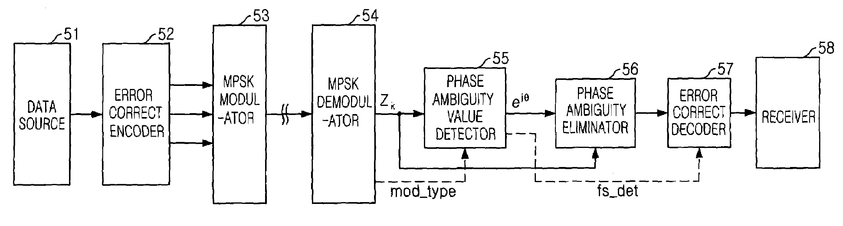
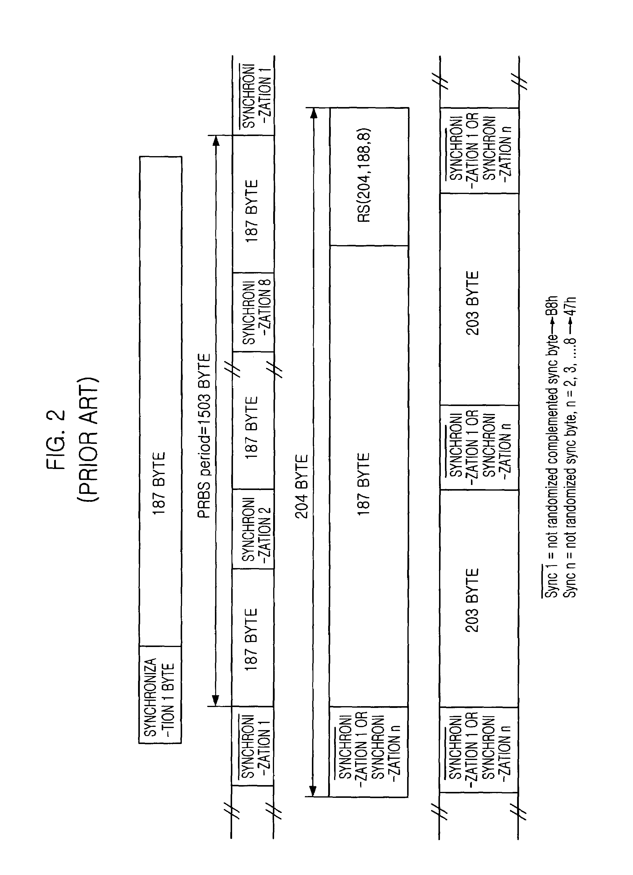
[0050]The apparatus of the present invention adaptively resolves the ambiguity of a various receiving data by detecting a phase ambiguity value directly from the receiving data. For directly detecting the phase ambiguity value, the apparatus uses a frame synchronization pattern detected during a demodulation process. The frame synchronization (Frame Sync) pattern as shown in FIG. 2 is used for detecting a start point of decoding and encoding of Reed-Solomon block code. Based on the frame synchronization pattern, offset information of demodulated signal can be detected. The offset informat...


PUM


Abstract

An apparatus for resolution of phase ambiguity is disclosed. The apparatus receives a modulated signal and resolves a phase ambiguity of the modulated signal while recovering the modulated signal to original data, wherein the apparatus includes a phase ambiguity detector for receiving demodulated data and frame synchronization information, and detecting a phase ambiguity value from the demodulated data based on a frame synchronization information; a phase ambiguity eliminator for receiving the phase ambiguity value and the demodulated data, and generating a phase ambiguity eliminated data by inverting the phase ambiguity value and multiplying the inverted phase ambiguity value and the demodulated data. The present invention can resolve a phase ambiguity occurred in various modulation modes including a burst mode communication with the same algorithm so it can effectively be implemented to an adaptive MODEM.

Description

FIELD OF THE INVENTION[0001]The present invention relates to an apparatus for adaptively resolving a phase ambiguity by directly detecting a phase ambiguity value from a various receiving signal.DESCRIPTION OF RELATED ARTS[0002]Recently, a national wide high speed information network has been built with a satellite and it has been used for a high definition television HDTV, a three-dimension TV, a multimedia communication based on a motion picture expert group-2 (MPEG-2) transport stream, an asynchronous transfer mode (ATM) and a high speed internet. The national wideband high speed information network requires reliable transmission channel and effective use of a satellite channel bandwidth. For effectively using the satellite channel bandwidth, a multi-dimension phase shift keying (M-PSK) of an adaptive modulation / demodulation (MODEM) technique is also required.[0003]A phase shift keying (PSK) demodulator recovers a phase and frequency offset by using a carrier recovery circuit, ho...

Claims


Application Information

Patent Timeline
IPC IPC(8): H04L27/00H03D3/18H04B1/00H04L27/10H04L27/22H04L1/00H04L27/227
CPCH04L1/0045H04L27/227H04L2027/0095H04L2027/0067H04L27/22
Inventor CHANG, DAE IGCHOI, EUN AKIM, NAE SOO
Owner ELECTRONICS & TELECOMM RES INST
Why Eureka
Try Eureka