
Optical disc head including a bowtie grating antenna and slider for optical focusing, and method for making

a technology of optical focus and optical disc head, applied in the direction of nanoinformatics, resonant antennas, instruments, etc., can solve the problems of large spot size, low maximum peak, and limited storage of information in magnetized medium

Inactive Publication Date: 2007-02-13
MEMS OPTICAL
View PDF19 Cites 23 Cited by
  • Summary
  • Abstract
  • Description
  • Claims
  • Application Information

AI Technical Summary

Benefits of technology

[0015]It is therefore an object of the present invention to provide a read / write system capable of maintaining a desired position of the read / write head to the target material using a shaped surface integrated with the read / write system.
[0017]It is further an object of the present invention to provide a gray scale slider delivery system that aids in the proper separation between a read / write system and a target medium, which integrates components, decreasing fabrication costs and increasing reliability.

Problems solved by technology

The storage of information in magnetized medium often is limited by the spot size of light intensity focused at the desired storage location.
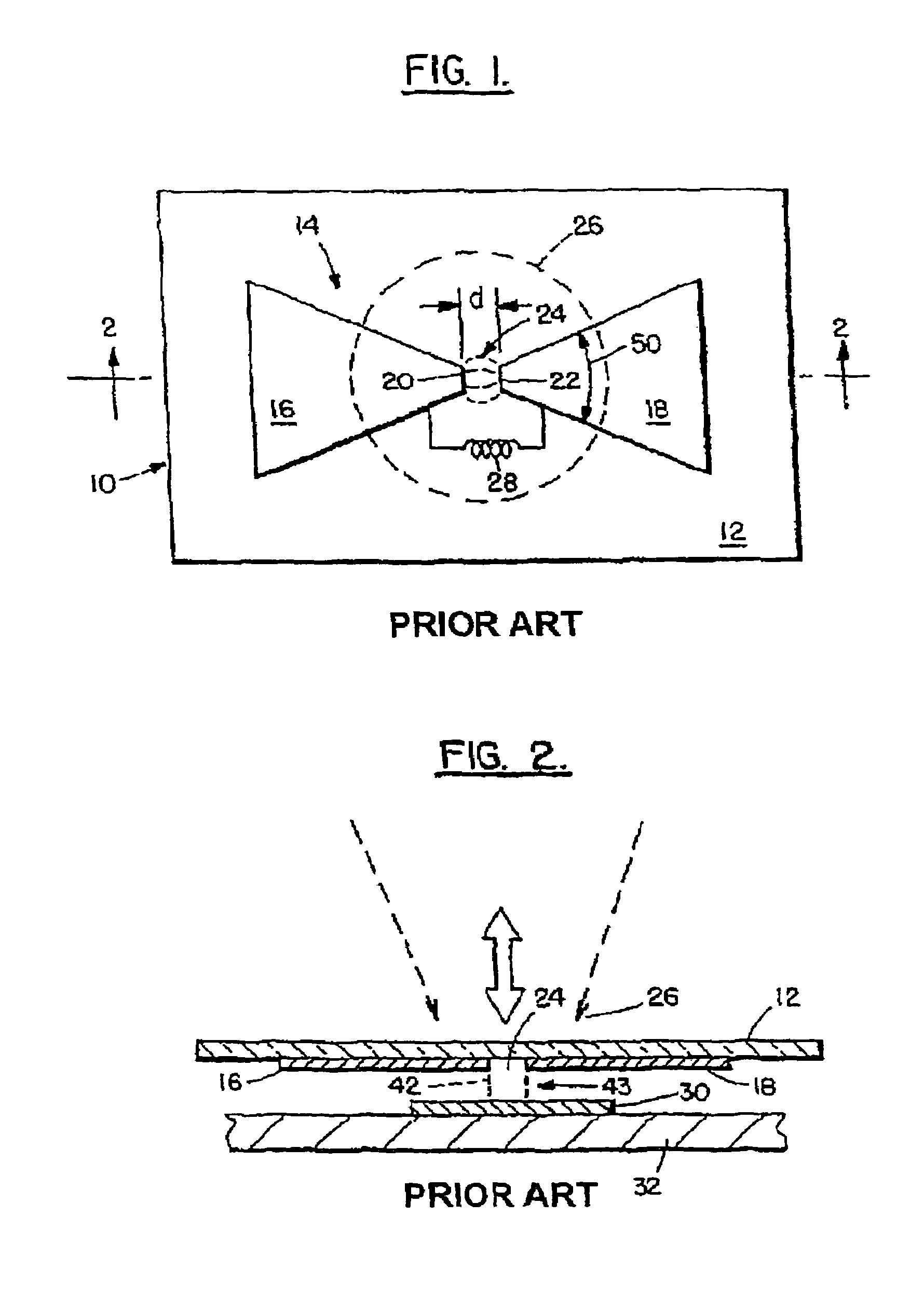
A disadvantage of multiple solid antennas is that the re-radiated field becomes depolarized during the superposition process resulting in lower than desired maximum peak in the irradiated field and a larger than desired spot size at the desired distance from the antenna.
Typical disadvantages of devices similar to that described are the size of the components; that the component parts must be accurately attached to each other; and the spot sizes are 200 nm or greater, which becomes the limiting factor of the recordable medium's storage space.
The need to assemble diverse components also substantially increased cost.

Method used


Image

  • Optical disc head including a bowtie grating antenna and slider for optical focusing, and method for making
  • Optical disc head including a bowtie grating antenna and slider for optical focusing, and method for making
  • Optical disc head including a bowtie grating antenna and slider for optical focusing, and method for making

Examples


Embodiment Construction

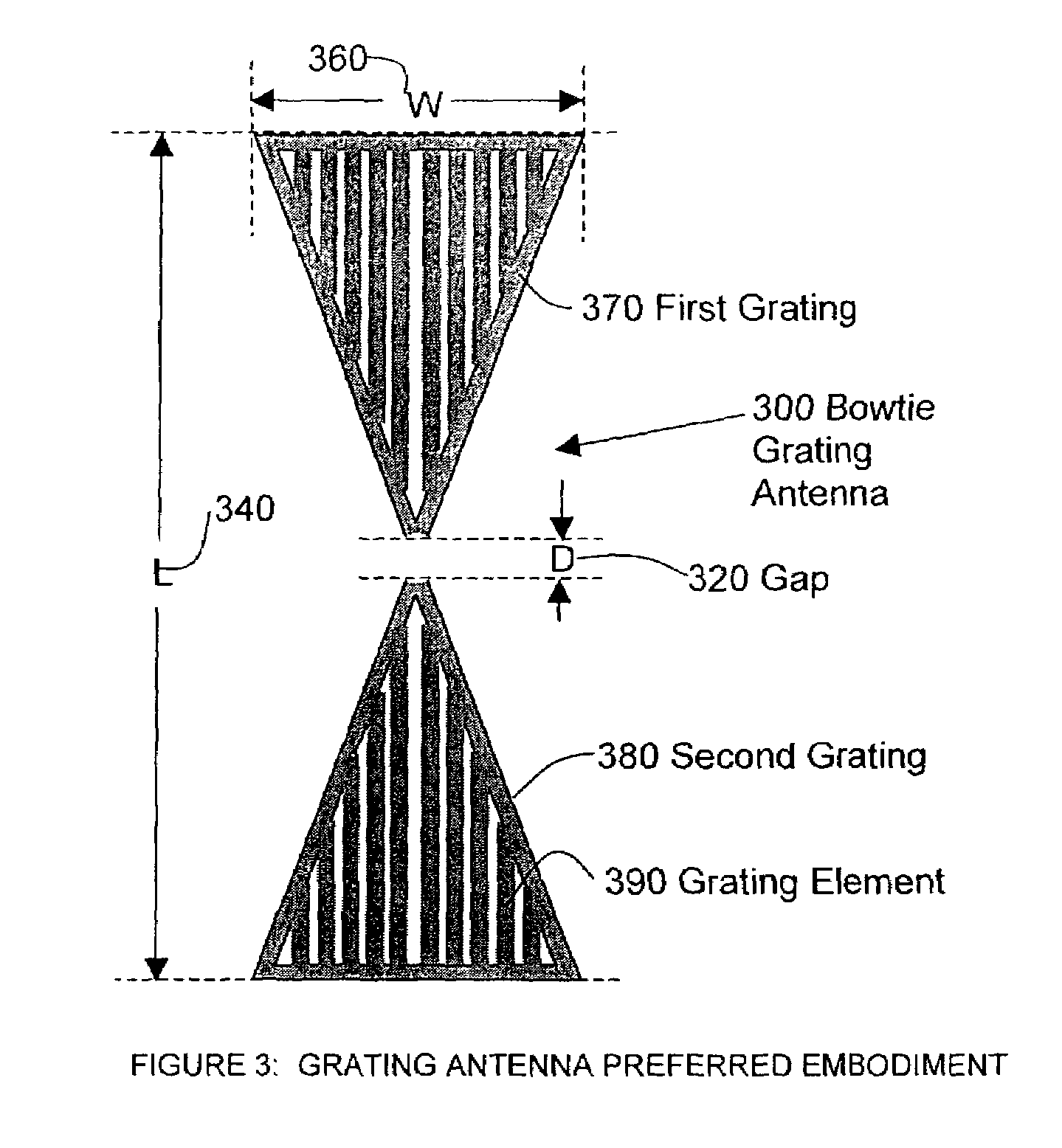
[0048]The present invention is a method / apparatus providing a delivery system that aids in the spacing between a read / write system and its target storage medium and / or uses grating antennas to create a small illumination spot size while maintaining a useful level of polarization.

[0049]Grating antennas are similar to diffraction gratings, which result in superpositions of transmitted fields. The superpositions result in maximum and minimum peaks of the irradiated field as a function of the position from the grating. The resultant peaks have more localized spatial positions than a diffraction grating or a solid two-piece antenna, as described in the background art, provides. Hence providing grating structure to an antenna results in localized peaks of intensity that are smaller in dimension than that which can be obtained by solid re-radiating displacement current antennas.

[0050]A grating antenna 300 according to a preferred embodiment of the present invention is illustrated in FIG. 3...


PUM

PropertyMeasurementUnit
sizesaaaaaaaaaa
sizeaaaaaaaaaa
lengthaaaaaaaaaa

Abstract

A slider system have been developed to aid in the spacing between read / write heads and the storage medium, and a grating antenna amplifier has been developed to improve illumination spot size and polarization characteristics. The grating antenna can be attached to a grayscale slider to obtain a distance between the illumination spot and antenna that lies in the near field region.

Description

[0001]This application claims priority on provisional Application No. 60 / 339,103 filed on Dec. 13, 2001, and Application No. 60 / 346,615 filed on Jan. 10, 2002, the entire contents of which are hereby incorporated by reference.BACKGROUND OF THE INVENTION[0002]1. Field of the Invention[0003]The present invention relates to optic antennas, optics lenses, and the positioning of electromagnetic readers and writers. More particularly, it relates to the use of microlayered optical lenses and shaped surfaces, a portion of which contains a continuously varied surface, coupled with an amplifying grating antenna as an optical head to create a localized optical spot of desired polarization, at a desired distance with a maximum peak in intensity.[0004]2. Background Information[0005]The storage of information in magnetized medium often is limited by the spot size of light intensity focused at the desired storage location. The intensity loosens the polarization of the medium so that a logical / anal...

Claims


Application Information

Patent Timeline
Patent Type & Authority Patents(United States)
IPC IPC(8): G11B7/18G02B6/12G11B7/12G11B7/135G11B7/22H01Q9/28
CPCB82Y10/00B82Y20/00G02B6/12H01Q9/28G11B7/1353G11B7/1387G11B7/22G11B7/1203G11B7/122
Inventor HARCHANKO, JOHNBANISH, MICHELE
Owner MEMS OPTICAL
Learn More