
Fingerprint identification method and system, and biometrics identification system

a fingerprint identification and biometric technology, applied in the field of fingerprint identification methods and systems, can solve the problems of physical property loss or theft, intelligence may be forgotten or stolen, and deterioration of handling convenience, and achieve the effect of high identification accuracy and low cos

Inactive Publication Date: 2007-02-06
NEC CORP
View PDF10 Cites 16 Cited by
  • Summary
  • Abstract
  • Description
  • Claims
  • Application Information

AI Technical Summary

Benefits of technology

[0013]The present invention was made in view of the above problems, and it has an object of providing a fingerprint identification system capable of higher identification accuracy with a fingerprint identification module, which has a predetermined identification accuracy and is inexpensive in cost.

Problems solved by technology

However, the technique of individual identification by using a physical property has a drawback in that the physical property may be lost or stolen.
In the identification technique using such intelligence as passwords, however, although the operation is easy and ready, the intelligence may be forgotten or stolen.
Particularly, for realizing high identification accuracy, the number of key digits has to be increased, thus extremely deteriorating the convenience of handling.
However, by so doing sufficient identification accuracy may not always be obtained.
In addition, in both the above techniques it is possible to improve the FAR, but doing so leads to deterioration (or increase) of the FRR.
To realize high identification accuracy, however, high performance processor and high capacity memory are necessary, leading to high system price.
At present, limitations are imposed on the processor performance and memory capacity that can be provided in the portable telephone set.
Therefore, it is difficult to mount a fingerprint identification module having high identification accuracy as noted above.

Method used


Image

  • Fingerprint identification method and system, and biometrics identification system
  • Fingerprint identification method and system, and biometrics identification system
  • Fingerprint identification method and system, and biometrics identification system

Examples


Embodiment Construction

[0027]Preferred embodiments of the present invention will now be described with reference to the drawings.

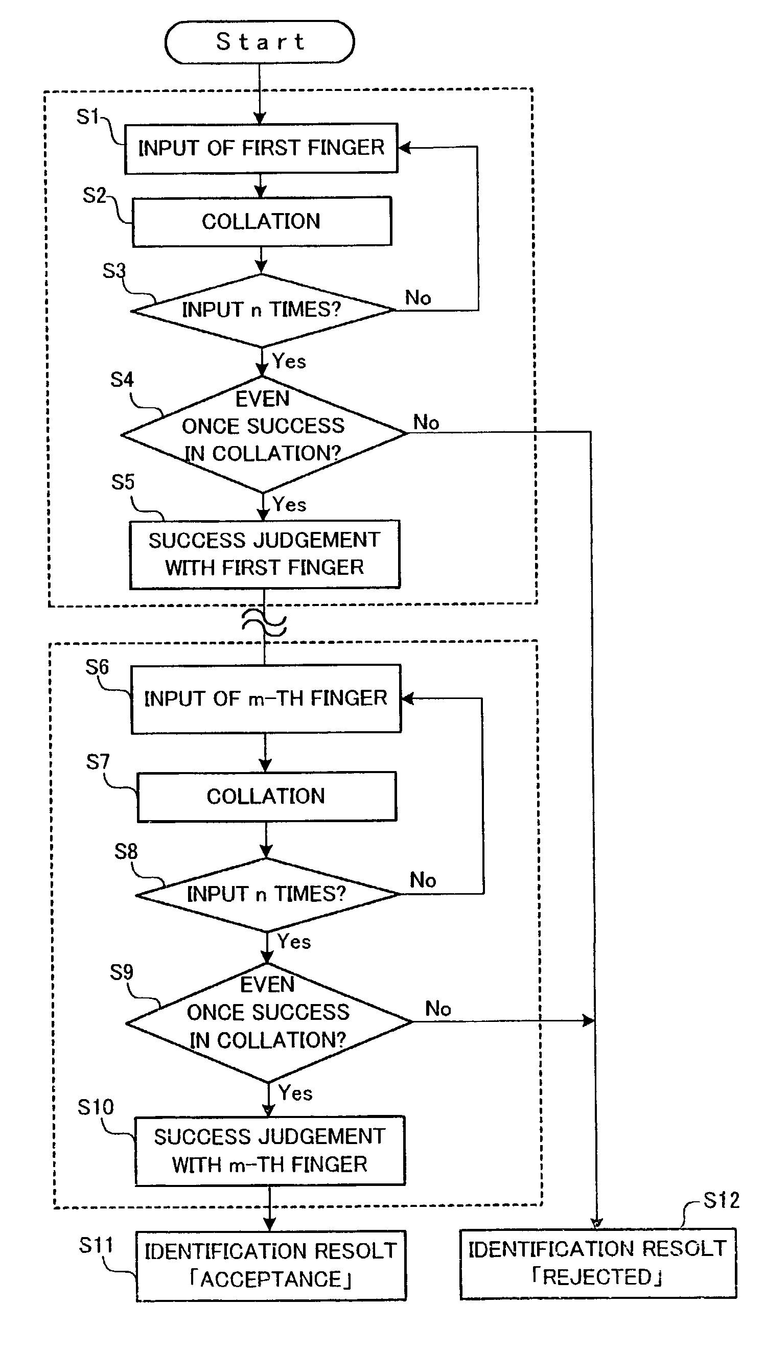
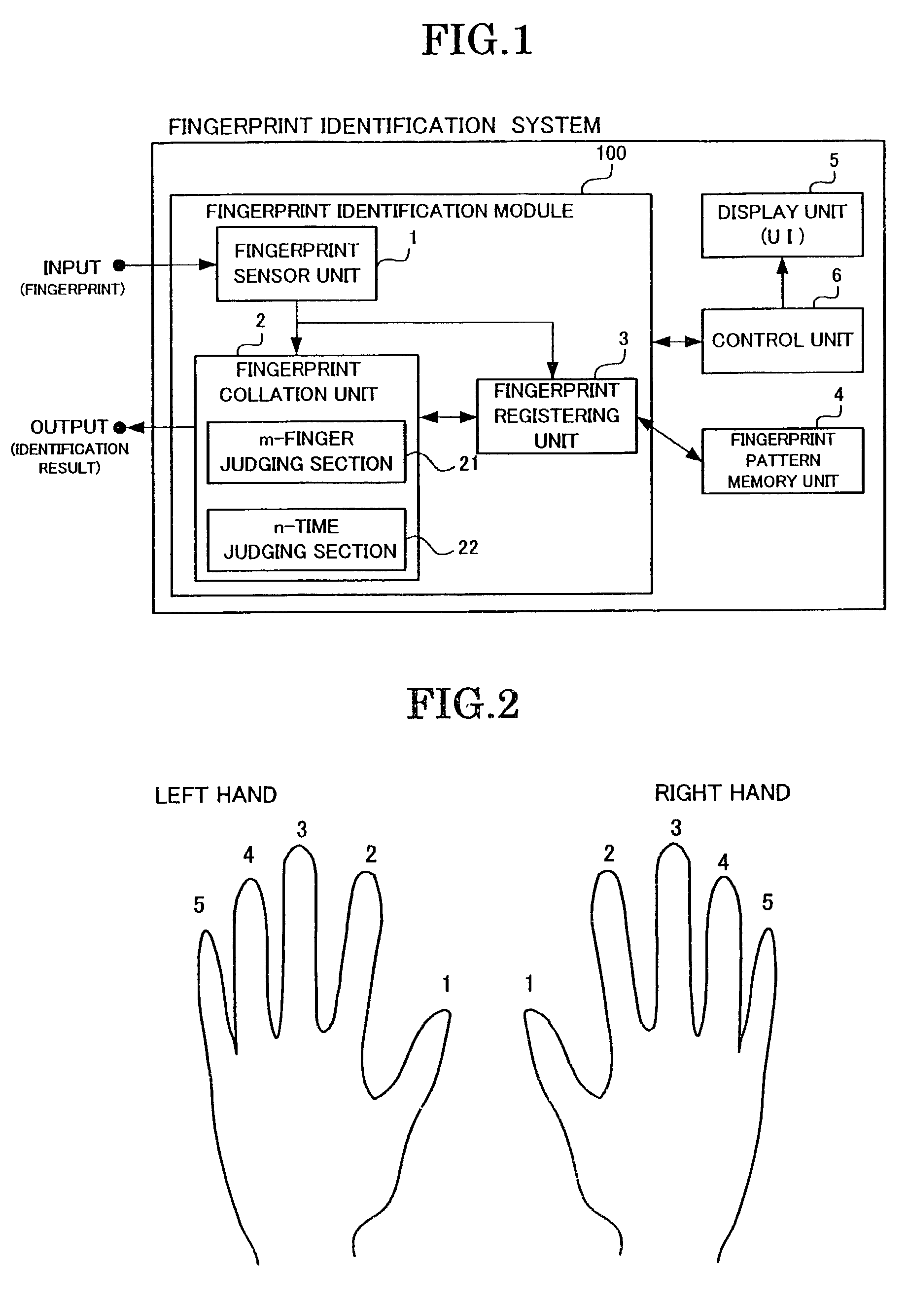
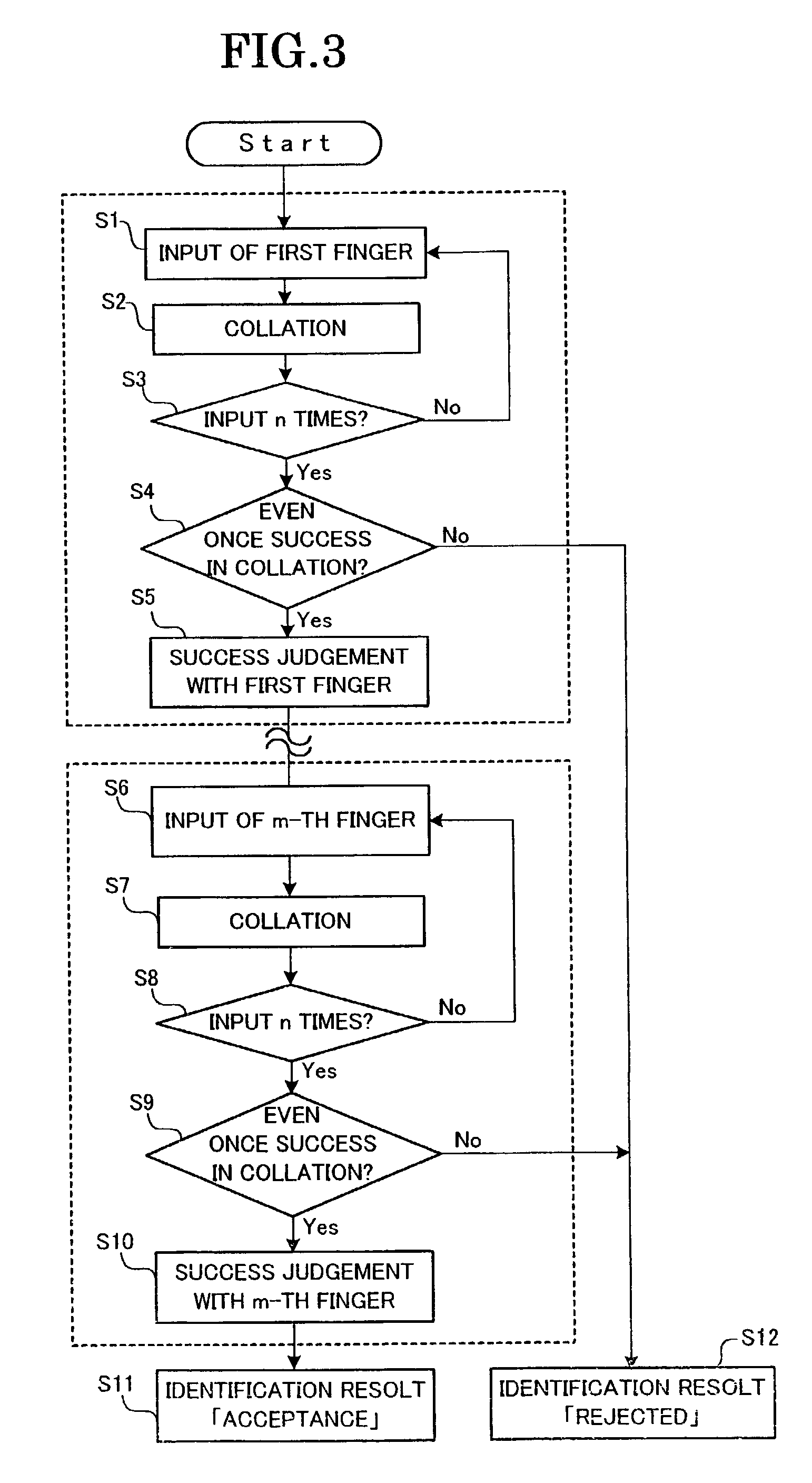
[0028]In the fingerprint identification system according to the present invention, at the time of the identification by the fingerprint identification module, a plurality of (i.e., m) different fingers of a person to be identified are used for fingerprint identification (see FIG. 2). For this reason, at the time of the fingerprint registration, fingerprint patterns of a plurality of (i.e., m or more) fingers are registered. In this system, at the time of the identification m fingers are collated. When collation of all the m fingers is successful, the identified person is certified (i.e., accepted) as being successful in identification, that is, the identification is judged to be successful in the whole system. Furthermore, in repetitive collation of each finger, a plurality of (i.e., n) times is allowed. When collation success is obtained with a finger even once, the collation a...


PUM


Abstract

A highly accurate identification system is built by using an identification module, which has predetermined values of FAR and FRR. A plurality of (m) biometrics are registered and managed. At the time of identification, a collation process is executed by using the m biometrics, and also a collation process is executed a plurality of (n) times with each biometrics. An identification result of the system is judged and outputted by combining the results of the m-biometrics collation and n-time collation trials. As conditions of judgment, when the collation is judged to be successful even once in the n-time collation trial, the collation is judged to be successful with respect to that biometrics. In the in-biometrics collation trial, when the collation is judged to be successful with respect to all the m biometrics, a judgment of identification success is given in the system as a whole.

Description

BACKGROUND OF THE INVENTION[0001]This application claims benefit of Japanese Patent Application No. 2001-359931 filed on Nov. 26, 2001, the contents of which are incorporated by the reference.[0002]The present invention relates to biometrics identification systems for individual identification and, more particularly, to fingerprint identification method and system.[0003]With recent rapid spread of portable telephone systems, it has been estimated to utilize portable telephone systems for purchasing products and making settlement there for in electronic business transactions. An individual identification system of high identification accuracy for making settlement in portable telephone system, thus has been demanded.[0004]As for the prior art individual identification system, there are various technical methods, such as a technique of individual identification by using a physical property such as a key or a card, a technique of individual identification by using person's intelligence...

Claims


Application Information

Patent Timeline
Patent Type & Authority Patents(United States)
IPC IPC(8): G06K9/00G06T7/00G06V10/764G07C9/00
CPCG07C9/00158G06K9/00087G07C9/37G06V40/1365G06V10/809G06V10/764G06F18/254G06F18/2415
Inventor OHBA, AKITOMO
Owner NEC CORP
Learn More