
Systems and methods for correcting gain error due to transition density variation in clock recovery systems

a clock recovery and gain error technology, applied in the field of processing data streams, can solve problems such as degrading loop performance, unpredictability of pll bandwidth, and uncertainty whether and when a transition will occur

Inactive Publication Date: 2007-02-06
AVAGO TECH WIRELESS IP SINGAPORE PTE
View PDF4 Cites 19 Cited by
  • Summary
  • Abstract
  • Description
  • Claims
  • Application Information

AI Technical Summary

Problems solved by technology

Thus, there is some uncertainty whether and when a transition will occur.
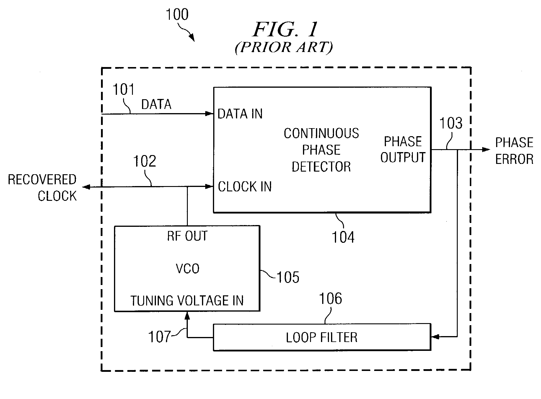
Unpredictable phase detector gain has at least two important deleterious effects.
First, the PLL bandwidth becomes unpredictable, because the PLL bandwidth is directly proportional to the phase detector gain.
This degrades loop performance (e.g., tracking error), which makes the loop more difficult to design.
Thus, the accuracy of the jitter measurement is questionable, when the data being measured does not have a predictable transition density.

Method used


Image

  • Systems and methods for correcting gain error due to transition density variation in clock recovery systems
  • Systems and methods for correcting gain error due to transition density variation in clock recovery systems
  • Systems and methods for correcting gain error due to transition density variation in clock recovery systems

Examples


Embodiment Construction

[0015]Before discussing embodiments in accordance with the invention in greater detail, a discussion of Nyquist's sampling theorem is presented for the convenience of the reader. The Nyquist sampling theorem is related to the problem of reconstructing a continuous analog waveform utilizing only discrete samples of that waveform's voltage taken at uniform time intervals. In Nyquist's sampling theorem, an assumption is made that the continuous analog waveform is bandlimited, meaning that there are no frequencies contained in the waveform that exceed an upper bound frequency (which defines the Nyquist bandwidth). Utilizing this assumption, Nyquist was able to prove that the continuous analog waveform can be perfectly reconstructed from these samples, if and only if the sampling rate is at least twice the Nyquist bandwidth. This sampling rate is referred to as the Nyquist rate. In practice, a phenomenon known as “aliasing” requires the sampling rate to be slightly higher than Nyquist's ...


PUM


Abstract

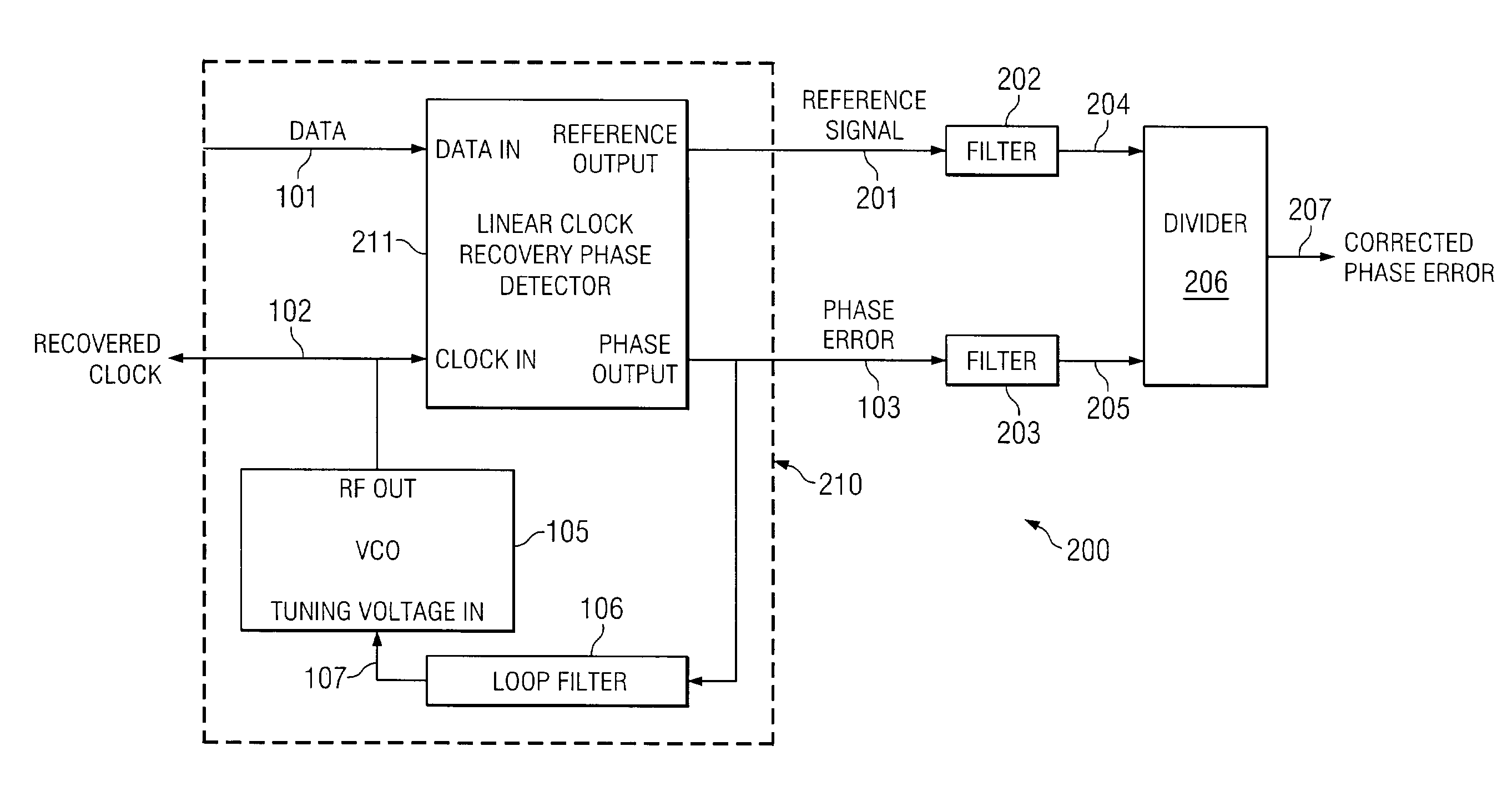
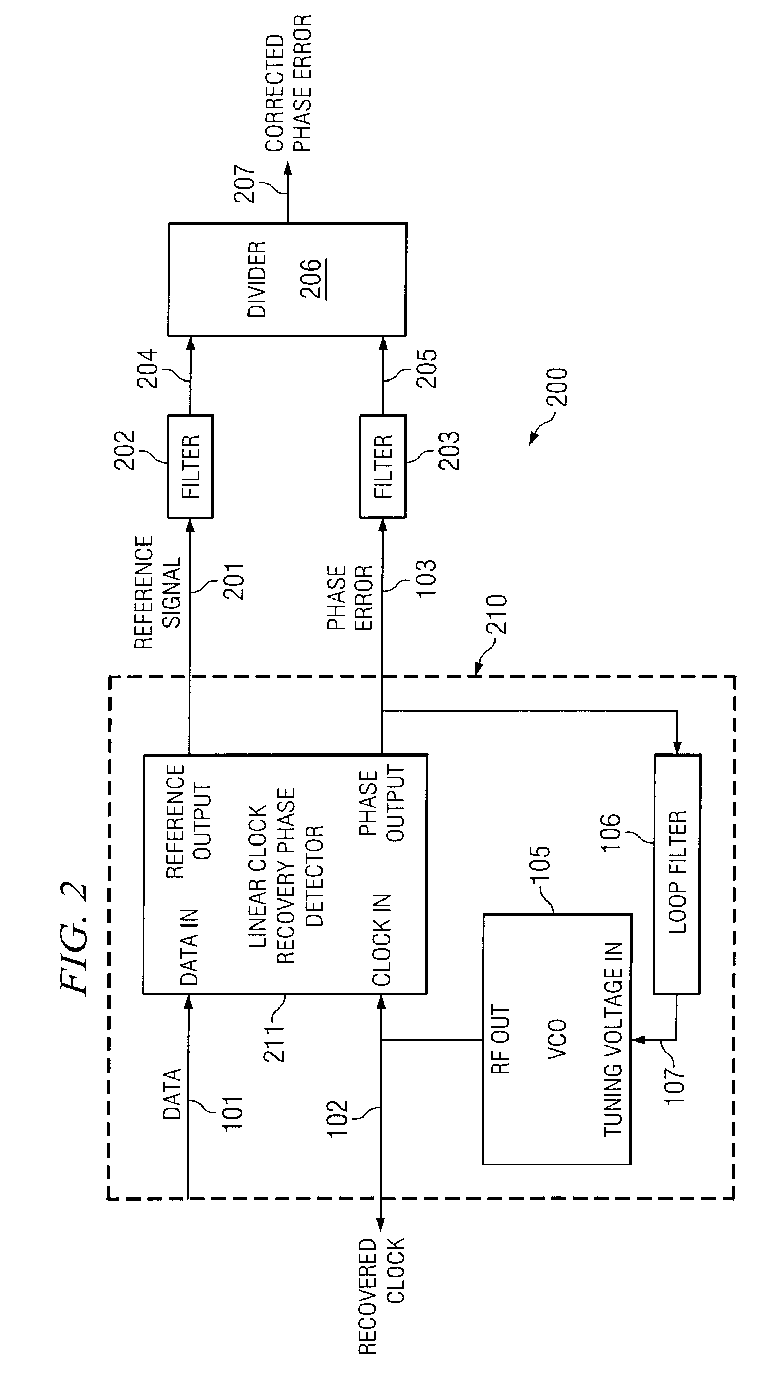
In one embodiment, the present invention is directed to a system for processing a data stream. The system comprises: a voltage controlled oscillator (VCO) that generates a VCO signal in response to a tuning signal; a phase detector that generates an error signal that is indicative of a phase difference between a data signal and the VCO signal; a first filter that filters a reference signal that is indicative of an occurrence of a data transition; a second filter that filters the error signal, wherein the first filter and second filter are low-pass filters that possess a bandwidth that approximately equals one half of the reciprocal of: a unit interval multiplied by a maximum run length; and a divider circuit that divides the filtered error signal by the filtered reference signal.

Description

RELATED APPLICATIONS[0001]The present application is related to concurrently filed, co-pending, and commonly assigned U.S. patent application Ser. No. 10 / 328,304, entitled “SYSTEM AND METHOD FOR DESIGNING AND USING ANALOG CIRCUITS OPERATING IN THE MODULATION DOMAIN;” U.S. patent application Ser. No. 10 / 328,363, entitled “PHASE LOCKED LOOP DEMODULATOR AND DEMODULATION METHOD USING FEED-FORWARD TRACKING ERROR COMPENSATION;” and U.S. patent application Ser. No. 10 / 328,358, entitled “SYSTEMS AND METHODS FOR CORRECTING PHASE LOCKED LOOP TRACKING ERROR USING FEED-FORWARD PHASE MODULATION;” the disclosures of which are hereby incorporated herein by reference.TECHNICAL FIELD[0002]The present invention is directed to processing a data stream that includes an embedded clock and, more particularly, to operating a phase locked loop (PLL) that exhibits predictable phase demodulation sensitivity in response to variation in symbol transition density.BACKGROUND OF THE INVENTION[0003]Non-return-to-z...

Claims


Application Information

Patent Timeline
Patent Type & Authority Patents(United States)
IPC IPC(8): H03D3/24H03L7/08H03L7/085H03L7/093H04L7/033
CPCH03L7/085H04L7/033H03L7/093
Inventor KARLQUIST, RICHARD K.
Owner AVAGO TECH WIRELESS IP SINGAPORE PTE
Learn More