
Aerosol generator having temperature controlled heating zone and method of use thereof

a generator and temperature control technology, applied in the field of aerosol generators, can solve the problems of not being able to deliver medicaments in liquid form, devices are not able to deliver medicaments to persons, and devices are not able to deliver materials

Inactive Publication Date: 2007-02-06
PHILIP MORRIS USA INC
View PDF217 Cites 133 Cited by
  • Summary
  • Abstract
  • Description
  • Claims
  • Application Information

AI Technical Summary

Problems solved by technology

While such devices may be acceptable for use in delivering medicaments in powder form, they are not suited to delivering medicaments in liquid form.
The devices are also, of course, not well-suited to delivery of medicaments to persons who might have difficulty in generating a sufficient flow of air through the device to properly inhale the medicaments, such as asthma sufferers.
The devices are also not suited for delivery of materials in applications other than medicament delivery.
A disadvantage of such aerosol generators, at least in medicament delivery applications, is the difficulty of properly synchronizing inhalation with pumping.
More importantly, however, because such aerosol generators tend to produce particles of large size, their use as inhalers is compromised because large particles tend to not penetrate deep into the lungs.
In propellant-based arrangements, however, a medicament may not be properly delivered to the patient's lungs when it is necessary for the user to time the depression of an actuator such as a button with inhalation.
Moreover, aerosols generated by propellant-based arrangements may have particles that are too large to ensure efficient and consistent deep lung penetration.
Although propellant-based aerosol generators have wide application for uses such as antiperspirant and deodorant sprays and spray paint, their use is often limited because of the well-known adverse environmental effects of CFC's and methylchloroform, which are among the most popular propellants used in aerosol generators of this type.
Most known aerosol generators are incapable of generating aerosols having average mass median particle diameters less than 2 microns.
Most known aerosol generators suited for drug delivery are incapable of delivering such high flow rates in the 0.2 to 2.0 micron size range.

Method used


Image

  • Aerosol generator having temperature controlled heating zone and method of use thereof
  • Aerosol generator having temperature controlled heating zone and method of use thereof
  • Aerosol generator having temperature controlled heating zone and method of use thereof

Examples


Embodiment Construction

[0027]When referring to the drawing figures, like reference numerals designate identical or corresponding elements throughout the several figures.

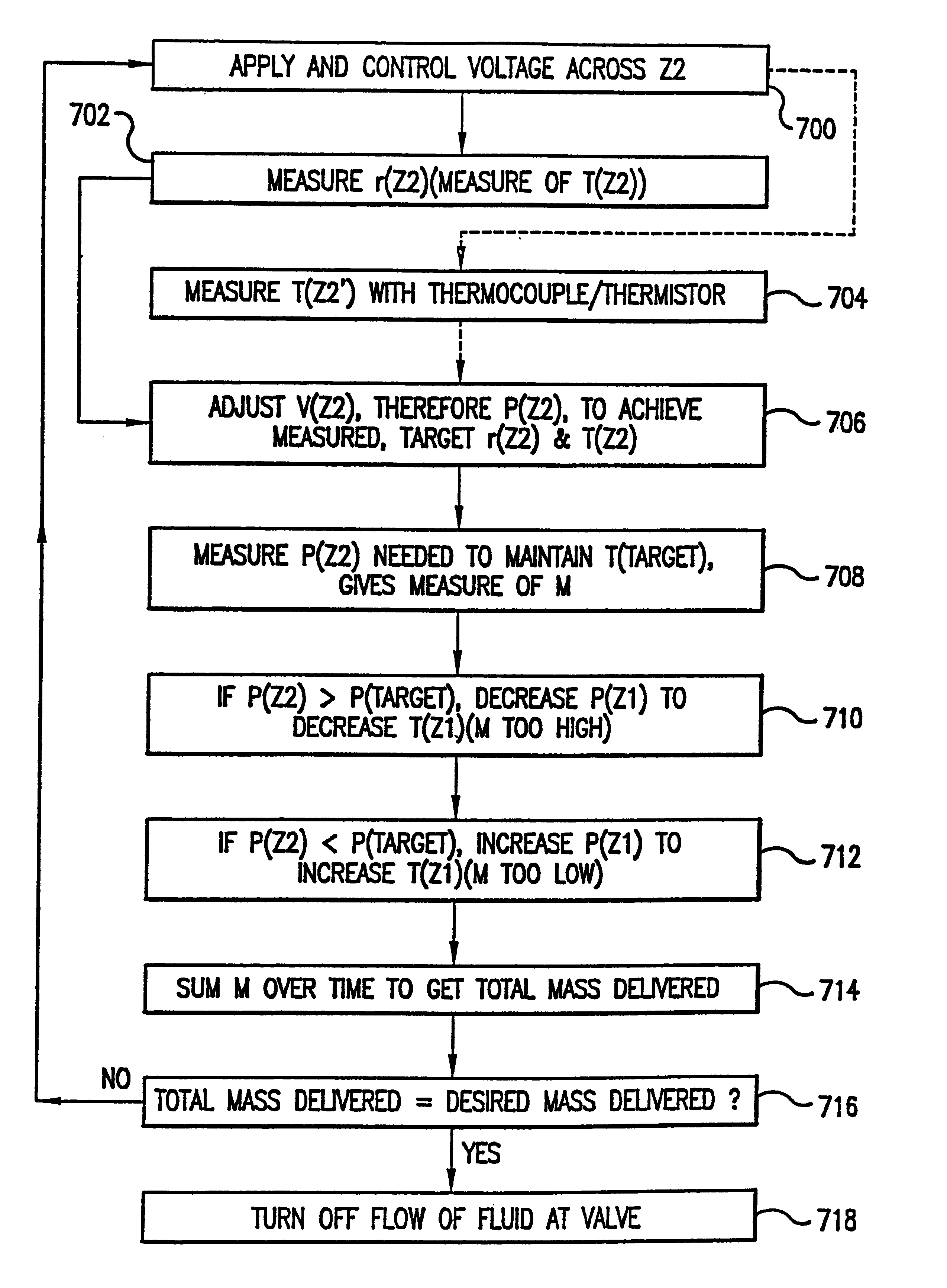
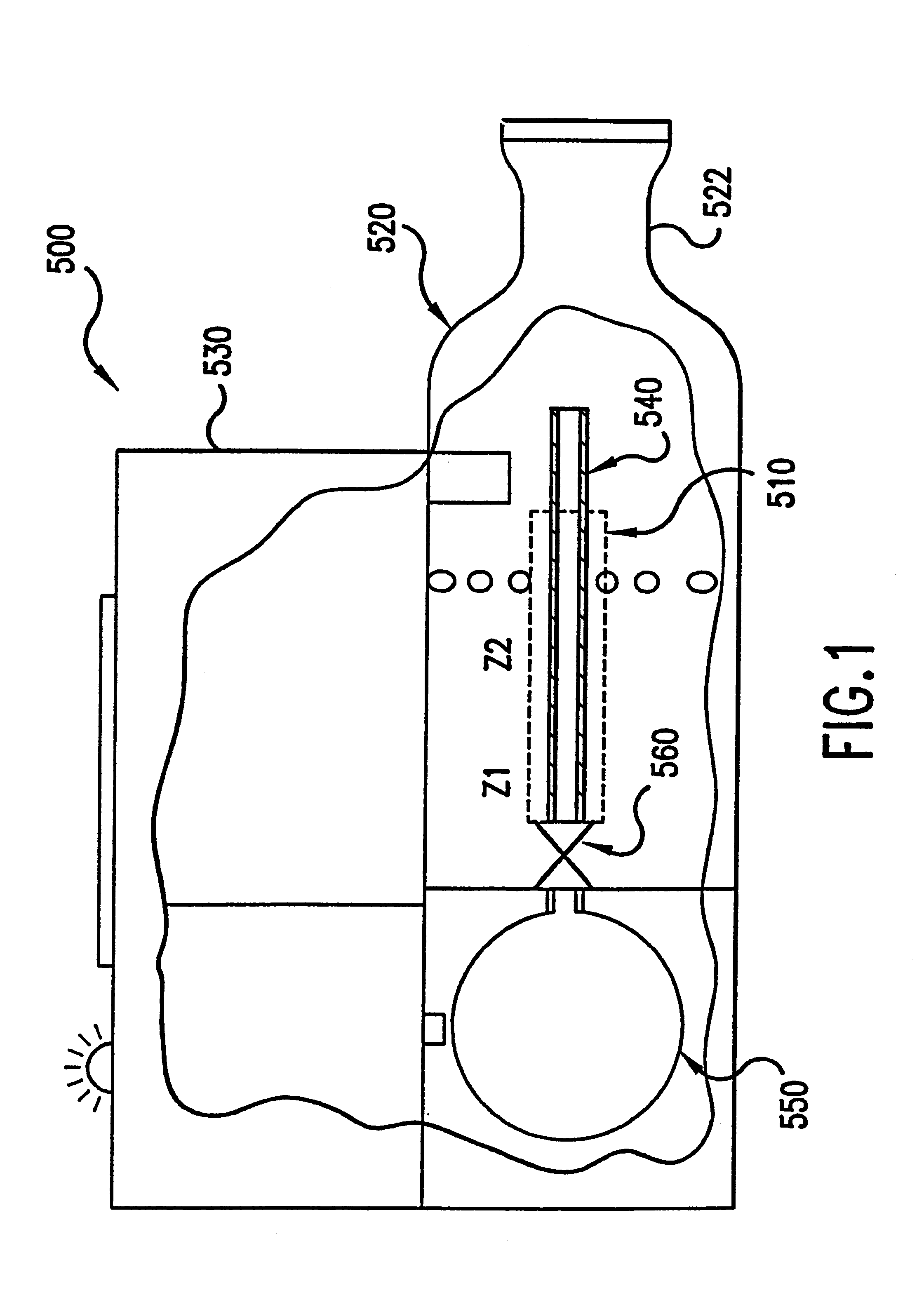
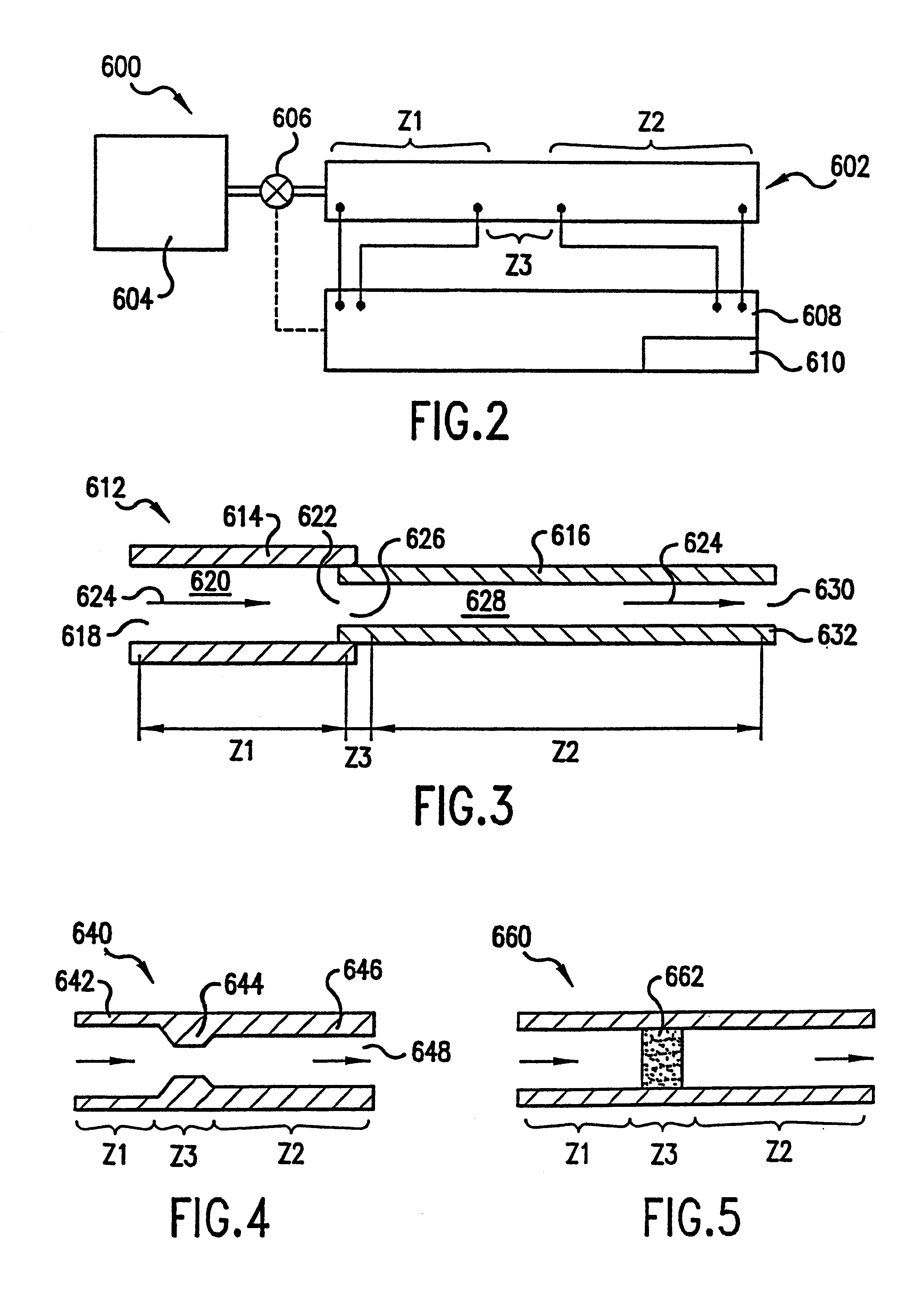
[0028]According to one aspect of the present invention, a capillary aerosol generator incorporates two heated zones. Each zone is heated by applying a voltage across a resistive element. The resistive elements may be film heaters, such as Pt heaters, applied to a supporting structure through which the fluid flows, e.g., flow chambers such as cylindrical or rectangular flow passages incorporating the film heaters. Fluid can be supplied to the generator, preferably at a substantially constant pressure, from a fluid source upstream of the generator. Alternatively, the fluid can be supplied at constant linear displacement rate by a syringe pump. The purpose of the second zone is to vaporize the fluid as it is transported through the tube and after exiting the tube forms an aerosol. Temperature in either heating zone can be measured directly by...


PUM


Abstract

A temperature and flow rate controlled capillary aerosol generator includes two heating zones optionally separated by a region in which a pressure drop is induced. Power is metered or applied to the downstream, second zone to achieve a target resistance, and therefore a target temperature, while power is metered or applied to the upstream, first zone to achieve a target mass flow rate exiting the second zone. A target temperature is achieved in the second zone to generate an aerosol from the liquid flowing through the generator at the desired mass flow rate.

Description

[0001]This application is a continuation divisional of Application No. 09 / 742,322, filed on Dec. 22, 2000 now U.S. Pat. No. 6,501,052.BACKGROUND OF THE INVENTION[0002]1. Field of the Invention[0003]The present invention relates generally to aerosol generators and, more particularly, to aerosol generators able to generate aerosols without compressed gas propellants and methods of making and using such aerosol generators.[0004]2. Brief Description of the Related Art[0005]Aerosols are useful in a wide variety of applications. For example, it is often desirable to treat respiratory ailments with, or deliver drugs by means of, aerosol sprays of finely divided particles of liquid and / or solid, e.g., powder, medicaments, etc., which are inhaled into a patient's lungs. Aerosols are also used for purposes such as providing desired scents to rooms, distributing insecticides and delivering paint and lubricant.[0006]Various techniques are known for generating aerosols. For example, U.S. Pat. No...

Claims


Application Information

Patent Timeline
IPC IPC(8): H05B1/02A61M11/02A61M11/04A61M15/02
CPCA61M11/041A61M11/042A61M15/025A61M15/02A61M11/007A61M2205/3372
Inventor COX, KENNETH A.NICHOLS, WALTER A.SPRINKEL, JR., F. MURPHYMCRAE, DOUGLAS D.SWEENEY, WILLIAM R.
Owner PHILIP MORRIS USA INC
Learn More