Eureka AIR delivers breakthrough ideas for toughest innovation challenges, trusted by R&D personnel around the world.

Method and apparatus for marking workpieces

a workpiece and marking technology, applied in the field of methods and marking workpieces, can solve the problems of large amount of required time, inability to use stamping dies, and inability to connect with stamping dies

Inactive Publication Date: 2007-01-30
MATE PRECISION TOOLING
View PDF46 Cites 36 Cited by
  • Summary
  • Abstract
  • Description
  • Claims
  • Application Information

AI Technical Summary

Benefits of technology

[0011]It is also advantageous in connection with the operation of the invention that the tool tip need be moved only once into its marking position, so that the number of punch strokes which must be performed by the punch press is considerably reduced. The results are reduced noise generation and reduced wear of the stroke driving mechanism.
[0017]It has been shown to be practical to guide the workpiece by means of at least one support roller which may be elastically spring-loaded in the area of the workpiece support table since, among other things, the support roller provides the required support for the workpiece while not hampering the displacement of the workpiece.
[0020]The counter-support preferably comprises at least one rotatable roller. The counter-support roller along with workpiece support table rollers facilitate movement of the workpiece during marking. Moreover the counter-support roller provides mobility without damage to the workpiece surface, and minimizes frictional losses such that they occur only at the contact point between the workpiece and counter-support roller.
[0023]The adjustable support makes possible the individual adaptation of the contact depth, for example in order to improve the clarity of the shapes formed in the workpiece, or to make possible an adaptation to the material of the workpiece.
[0025]Alternatively, a marking tool made of brass, plastic or any other material which is incapable of cutting the workpiece may be utilized for the purpose of marking a shape in a protective covering placed over the workpiece without damaging the workpiece.

Problems solved by technology

In this connection the use of stamping dies is not always practical because the stamping is often also visible on the back of sheet metal workpiece.
Difficulties in connection with stamping dies occur particularly when it is intended to punch parts of different lengths out of a sheet metal workpiece (e.g., in order to minimize waste) and wherein a certain orientation of the marking on the workpiece is desirable.
Besides the large amount of required time and the increased wear of the driving mechanism for the stroke, which is driven in a quasi load-free manner, the loud noise is considered to be a disadvantage.
A coarser dot matrix does simplify the marking process, but it also results in a more unsatisfactory matrix.
However, if this were done, the space available for the main punching operation would be reduced and the progress of the main punching operation would be made more difficult.
Also, this marking device could only operate within a limited portion of the area of the punch press so that movement of the sheet metal workpiece in order to apply markings on different areas thereof would become more difficult.

Method used


Image

  • Method and apparatus for marking workpieces
  • Method and apparatus for marking workpieces
  • Method and apparatus for marking workpieces

Examples


Embodiment Construction

[0033]Referring now to the drawings, like elements are represented by like numerals throughout the several views.

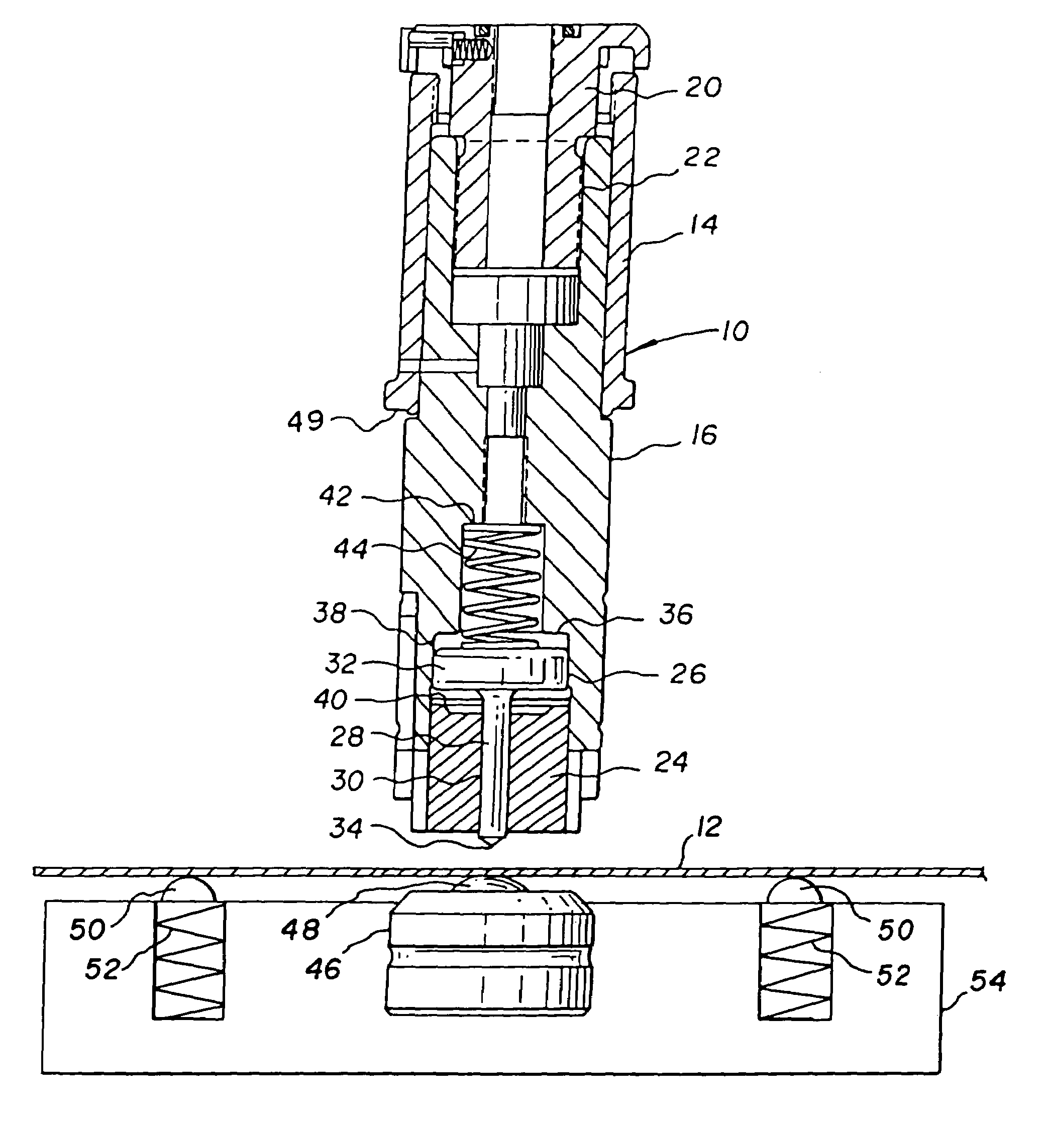
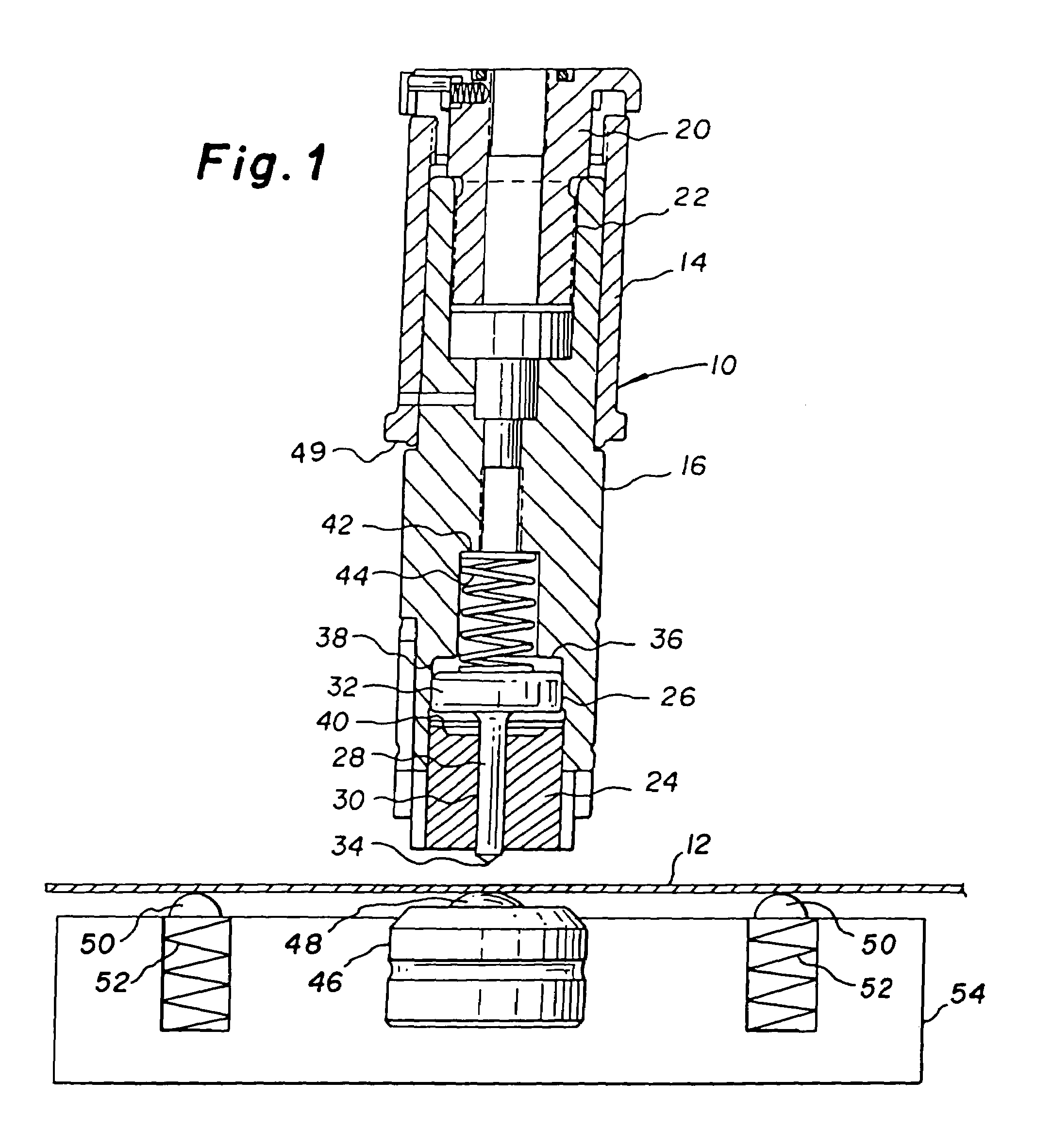
[0034]Referring to FIG. 1, the marking tool has a guide bush 14, in which a support 16 is axially guided, and a driving head 20, which are in engagement with each other via a threaded connection 22. By means of a guide insert 24, the support 16 holds a marking tool 26, which is axially movable with respect to the support 16 and has a tool shaft 28 which is guided in an appropriately fitted bore 30 of the guide insert 24, a pressure plate 32, formed at the top of the shaft 28, as well as an inscribing element 34, seated on the free lower end of the shaft 28. The tip 34 of the marking tool can be of different constructions, depending on the type of mark to be made. In a first embodiment, the tip 34 may be made of a hard material and shaped as a pointed cone to be used as an inscribing element. As an inscribing element, 34 can be made, for example, of a diamond, boron nitrid...


PUM

PropertyMeasurementUnit
Pressureaaaaaaaaaa
Areaaaaaaaaaaa
Elasticityaaaaaaaaaa

Abstract

A method and an apparatus are provided for marking a sheet-shaped workpiece using a marking tool. The marking tool is mounted in a punch holder of a punch press and a counter-support is fixed in place on a side opposite of a marking surface of the workpiece to be marked. The surface of the workpiece is marked by displacing the workpiece in its plane while engaging the marking tool with the workpiece. In one form, a support roller provides counter-support. In another form, an elastic element is cooperatively associated with the punch stroke of the punch press to translate an exactly defined contact pressure force between the tool tip and the workpiece to be marked.

Description

FIELD OF THE INVENTION[0001]This application is a continuation of application Ser. No. 09 / 881,678 filed Jun. 18, 2001 now abandoned which is a continuation-in-part of prior application Ser. No. 09 / 688,094 filed Oct. 16, 2000 now abandoned.[0002]The present invention relates to a method and an apparatus for marking workpieces on a punching press, wherein the marking tool is forced by means of the punching stroke either against the surface of the workpiece or a certain depth into the surface of the workpiece. The workpiece, which is generally a piece of flat sheet metal, is displaced within its plane in order to create a straight or curved marking line.BACKGROUND OF THE INVENTION[0003]There is an increasing demand for altering the surface of workpieces, including as one example, providing workpieces with individual identifications. In this connection the use of stamping dies is not always practical because the stamping is often also visible on the back of sheet metal workpiece. Diffic...

Claims


Application Information

Patent Timeline
IPC IPC(8): C03B33/027B21C51/00B21D17/02B44B5/00
CPCB21C51/005B21D17/02B44B5/0019B41J3/385Y10T29/5116Y10T83/0304Y10T83/0333Y10T83/02Y10T83/023Y10T83/0348
Inventor SCHNEIDER, ALBRECHT
Owner MATE PRECISION TOOLING
Why Eureka
Eureka Blog
Learn More