
Automated approach to resolving artificial algebraic loops

a technology of artificial algebra and loops, applied in the direction of source code creation/generation, visual/graphical programming, instruments, etc., can solve the problems of thrown execution errors, disallow the use of blocks, and are not generally suitable for describing dynamic system behavior

Active Publication Date: 2007-01-23
THE MATHWORKS INC
View PDF4 Cites 35 Cited by
  • Summary
  • Abstract
  • Description
  • Claims
  • Application Information

AI Technical Summary

Benefits of technology

The present invention provides an efficient method for automatically resolving artificial algebraic loops in electronic devices. The invention identifies potential artificial algebraic loops and proposes an artificial algebraic loop solution that modifies the way functions in the process execute. The solution can include rerouting functions, inserting delays, and switching the order of functions to prevent the occurrence of the loop. The invention also includes a representation of the process in block diagram and equation formats, and an execution order for the functions based on their update calls, derivatives, and zero-crossing calls. The technical effects of the invention include improved efficiency and automation for resolving algebraic loops in electronic devices.

Problems solved by technology

For instance, flow-charts are block diagrams used to capture process flow and are not generally suitable for describing dynamic system behavior.
A restrictive flag disallows the use of blocks in certain modeling contexts.
If there are any unresolved parameters, execution errors are thrown at this point.
If not, an error is issued.
For instance, if an Integrator block is implemented to only accept numbers of double precision datatype, then this block will error out if it is driven by a block that produces single precision data, unless the user has asked for an implicit data conversion.
Attempting to correlate data dependencies directly to the signals found within a block diagram is incorrect and leads to the conclusion that Simulink® does not satisfy data dependencies, i.e., the execution of the operations or block methods does not satisfy data dependencies if one interprets signal connectivity as specifying data dependencies.
It should be noted that the traceability associated with interpretive execution comes at the price of increased overhead in the form of additional execution-related data-structures and messaging in the engine.
Such bugs prove much more expensive to track and fix once the system has been implemented in hardware.
Additionally, the use of rate transition blocks restricts the connection of blocks with different rates.
Otherwise, the outputs of the model could lead to false conclusions about the behavior of the system under investigation.
This might lead an investigator to false conclusions about the physics of the bouncing ball.
In the case of Fixed-step solvers, there is no notion of zero-crossing detection and one is not guaranteed to find all points of discontinuity.
While it is theoretically possible to have Variable-step solvers in the context of multitasking, such a combination is not employed in practice.
This is because the step-size for such solvers can become very small making it impossible to keep up with the real-time constraint that generally goes along with multitasking execution.
An added complication is that the integration step in such solvers is iterative and takes varying amounts of time at each step of the execution.
Additionally, they are not usually employed in systems that need to operate in real-time.
Such systems range from simple to highly complex systems.
However, this is an inefficient and time consuming approach that cannot provide a fixed computational load because it relies upon iteration, and is therefore not suited for, e.g., real-time applications.
Failure to sort blocks such that these direct feedthrough relationship hold will require multiple output method evaluations to get the correct answer, resulting in inefficient execution.
Because of the requirement that input signals to direct feedthrough ports of blocks must be computed prior to obtaining an output calculation, and despite care in sorting blocks in a block diagram model, there is a tendency for algebraic loops to occur.
However, most algebraic loops cannot be solved by inspection.
However, if not prohibitively difficult, this also can be time consuming, especially in complex systems, because of the likelihood that there are a significant number of algebraic loops to either solve or eliminate.

Method used


Image

  • Automated approach to resolving artificial algebraic loops
  • Automated approach to resolving artificial algebraic loops
  • Automated approach to resolving artificial algebraic loops

Examples


Embodiment Construction

[0156]An illustrative embodiment of the present invention relates to an automated solution for addressing artificial algebraic loops in a block diagram or text or equation based execution, simulation, or modeling system. The automated solution involves scanning a model to identify each occurrence of a potential artificial algebraic loop. Once each potential artificial algebraic loop is identified, the present invention partitions the potential artificial algebraic loop in a regular part and a direct feedthrough part, the output of the latter is computed in the update phase of the simulation to obtain a correct output of all blocks involved. More specifically, when the blocks of the model are tasked with calculating an output, the present invention disregards the blocks in the direct feedthrough portion. Then, when tasked to update the state, the blocks in the direct feedthrough part first compute their output to obtain correct output values of all blocks in the model.

[0157]The phras...


PUM


Abstract

A method and apparatus for resolving artificial algebraic loops in model executions include providing an executable process having a plurality of functions. An analysis step identifies whether the process includes at least one potential artificial algebraic loop. If at least one potential artificial algebraic loop exists in the process, an artificial algebraic loop solution manipulates the order or manner by which the functions are executed to eliminate or otherwise resolve the artificial algebraic loop.

Description

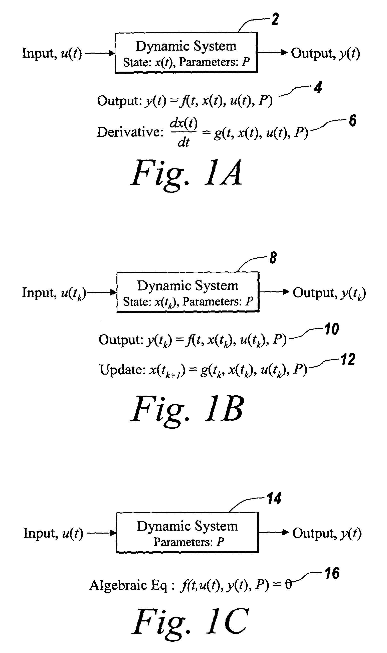
FIELD OF THE INVENTION[0001]The present invention relates to a method and apparatus suitable for resolving algebraic loops in execution of a model, and more particularly to a method and software application for identifying and resolving artificial algebraic loops in model executions.BACKGROUND OF THE INVENTION[0002]Dynamic systems are typically modeled in simulation environments as sets of differential, difference, and / or algebraic equations. At any given instant of time, these equations may be viewed as relationships between the system's output response (“outputs”), the system's input stimuli (“inputs”) at that time, the current state of the system, the system parameters, and time. The state of the system may be thought of as a numerical representation of the dynamically changing configuration of the system. For instance, in a physical system modeling a simple pendulum, the state may be viewed as the current position and velocity of the pendulum. Similarly, a signal-processing syst...

Claims


Application Information

Patent Timeline
Patent Type & Authority Patents(United States)
IPC IPC(8): G06F17/10G06F9/44G06F17/13G06F17/50
CPCG06F8/34G06F17/5009G06F17/10G06F30/20
Inventor MOSTERMAN, PIETER J.CIOLFI, JOHN EDWARD
Owner THE MATHWORKS INC
Learn More