Automatic surgical device and control assembly for cutting a cornea

Inactive Publication Date: 2007-01-23
HELLENKAMP JOHANN F
View PDF324 Cites 374 Cited by
  • Summary
  • Abstract
  • Description
  • Claims
  • Application Information

AI Technical Summary

Benefits of technology

[0013]The present invention is designed to satisfy the needs which remain in the art of microkeratome devices used to cut the cornea of a patient's eye. In this regard, the present invention is directed towards an improved microkeratome which is able to cut and raise a microscopicly thin layer of corneal tissue in a manner that results in very fine, smooth and almost undetectable cut corneal tissue edges. Along these lines, the present invention is seen to include structure for retaining and positioning the eye on which surgery is to be performed, a cutting head assembly, including a cutting element positioned therein, for cutting the cornea of the eye, and in some embodiments a coupling member for detachably coupling the retaining and positioning means and cutting head assembly while permitting movement of the cutting head assembly relative to the retaining and positioning means along a generally arcuate path.
[0015]The present invention further comprises a driving assembly for driving the cutting head assembly over the retaining and positioning assembly, and in the preferred embodiment, may include a stop assembly, which is structured and disposed to limit movement of the cutting head assembly across the retaining and positioning assembly. The stop assembly may be formed on the cutting head assembly and may be structured and disposed to engagingly abut a portion of the guide assembly so as to limit further movement of the cutting head assembly at a point before the cutting element has passed completely over the cornea of the eye, thereby forming the corneal flap on the eye undergoing surgery. In the preferred embodiment, the drive assembly is operably connected to the cutting head assembly at a top surface thereof and is capable of stopping and reversing the direction of movement of the cutting head assembly once the stop assembly has prevented movement of the cutting head assembly in a first direction across the retaining and positioning assembly.
[0016]In addition, the present invention is directed towards an improved microkeratome cutting blade assembly that permits quick and easy installation and removal from the microkeratome housing, without excessive manipulation, and which provides an effective cut and range of movement. Preferably, the cutting blade assembly of the present invention is seen to comprise an improved cutting blade and blade holder. The cutting blade comprises a front portion that includes a sharp, forward cutting edge, a rear, trailing portion having a rear edge, and a pair of side edges, at least one of which extends and tapers between the front and rear trailing portions. The cutting blade, which may be secured to the blade holder in any operable method, may further include at least one aperture formed therein, and preferably, a pair of apertures disposed in the rear, trailing portion in substantially aligned relation with one another. Preferably, the cutting blade is substantially flat and made of stainless steel, with the front portion of the cutting blade having an overall dimension which is larger than the rear trailing portion. The blade holder of the improved cutting blade assembly is formed so that an underside thereof is secured to the cutting blade, such as at the at least one aperture on the cutting blade, and so that a top side of the blade holder includes structure for being operably driven by the drive assembly of the microkeratome device, which may comprise a recess formed within the blade holder. In the preferred embodiment, the blade holder will be molded of a plastic material and will be press fit during manufacture into the at least one aperture on the cutting blade so as to provide an integrally formed cutting blade assembly. In a most preferred embodiment, the cutting blade assembly of the present invention will additionally comprise a tool which facilitates the removal of the cutting blade and blade holder from a sterile packing container and the insertion thereof in a microkeratome device, while maintaining sterility.
[0017]The present invention is also directed towards a control assembly for a microkeratome device that is capable of detecting problems encountered during the surgical cutting of the cornea and either shutting off power supplied to the device, if appropriate, or ensuring that power and / or a vacuum continue to be supplied to the device, if appropriate.

Problems solved by technology

Until about twenty years ago, refractive errors of light passing through the eye could only be treated with eyeglasses or contact lens, both of which have well known disadvantages for the user.
The reasons are primarily two-fold: first, the possibility exists that when the corneal cap is put back in place on the cornea, it will not be aligned properly with the remaining corneal tissues, which has several drawbacks for the patient, and second, the possibility exists that the corneal cap will become lost during the surgery, and if that occurs, the consequences for the patient are catastrophic.
This excessive manipulation required of known microkeratome devices is not conducive, however, to maintaining the proper sanitary and sterilized state required for surgery.
Moreover, in manipulating the access means of certain known microkeratome devices, some surgeons have unintentionally caused the cutting blade to become dislodged, or worse, have even bent the cutting blade, thereby requiring the assembly process to start over again.
This factor tends to only exacerbate the problems encountered in the art in that these known blade holding mechanisms should also be removed from the microkeratome device following a surgery in order to be properly cleaned and / or sterilized for subsequent use.
The assembly and disassembly of these mechanisms are not only tedious and time consuming, but are fraught with the difficulties of maintaining sterilization and ensuring proper re-assembly.
Known microkeratome devices are thought to have other, fairly significant deficiencies as well.
For example, when a surgery on a patient's eye is underway, at times the suction or vacuum provided to temporarily attach the positioning ring to the cornea is either broken or interrupted.
Given the precision cutting which is needed for such surgeries, however, it is highly undesirable, for the eye to continue to be cut during such situations.
Moreover, if surgery on a patient's eye is proceeding well, but there is sudden power loss, any such control assembly should enable the microkeratome device to continue functioning during the rather short duration of the operation, without interruption, both in terms of continuing to ensure a power supply to the device and a supply of vacuum to the positioning ring.

Method used


Image

  • Automatic surgical device and control assembly for cutting a cornea
  • Automatic surgical device and control assembly for cutting a cornea
  • Automatic surgical device and control assembly for cutting a cornea

Examples


Embodiment Construction

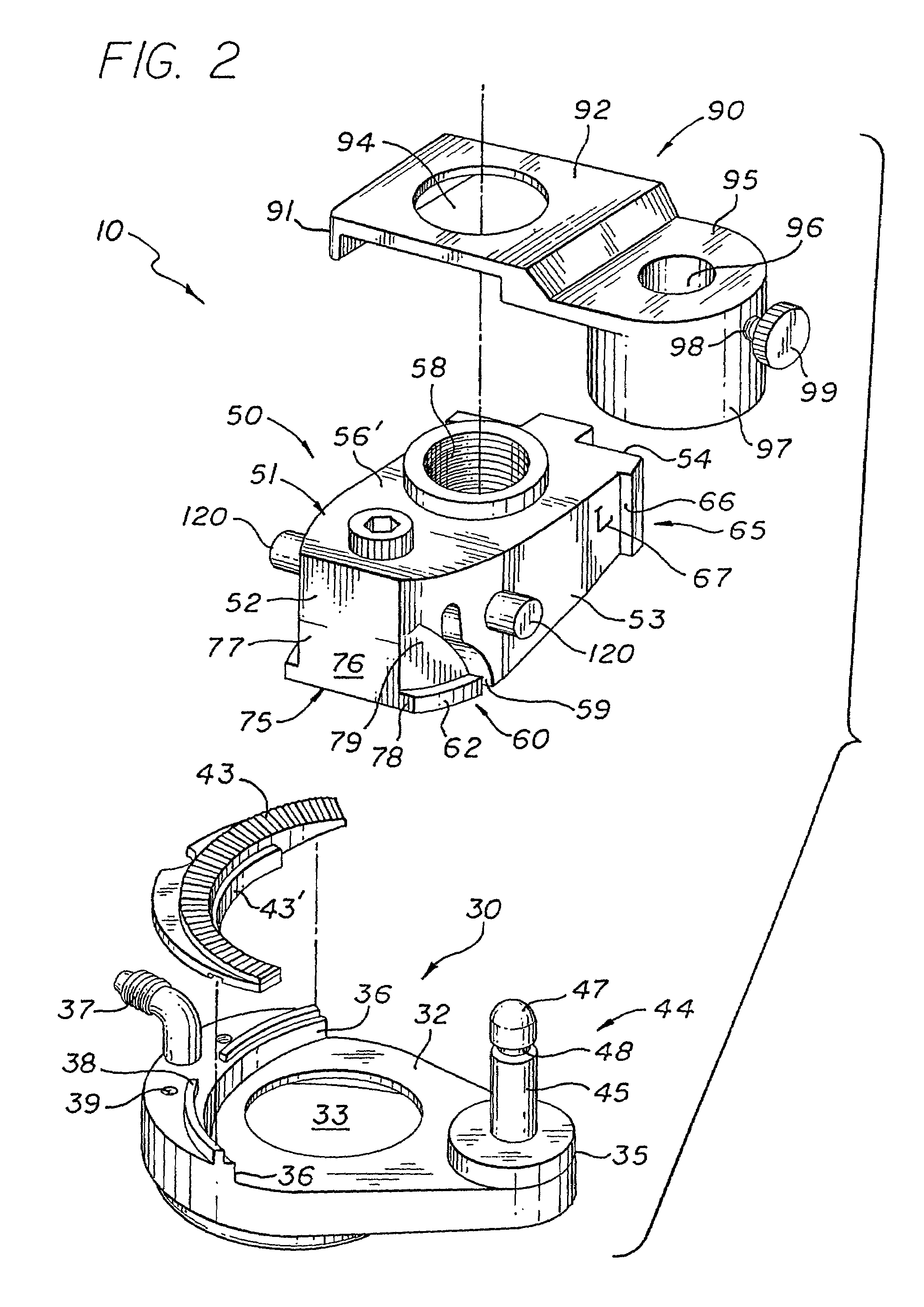
[0037]As illustrated throughout the Figures, the present invention is directed towards an improved automatic microkeratome device for smoothly cutting the cornea of an eye, generally indicated by reference numeral 10, and towards a cutting blade assembly therefor, generally indicated by reference numeral 105, and towards a control assembly therefor, generally indicated by reference numeral 200.

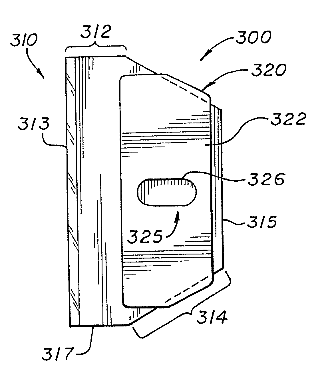
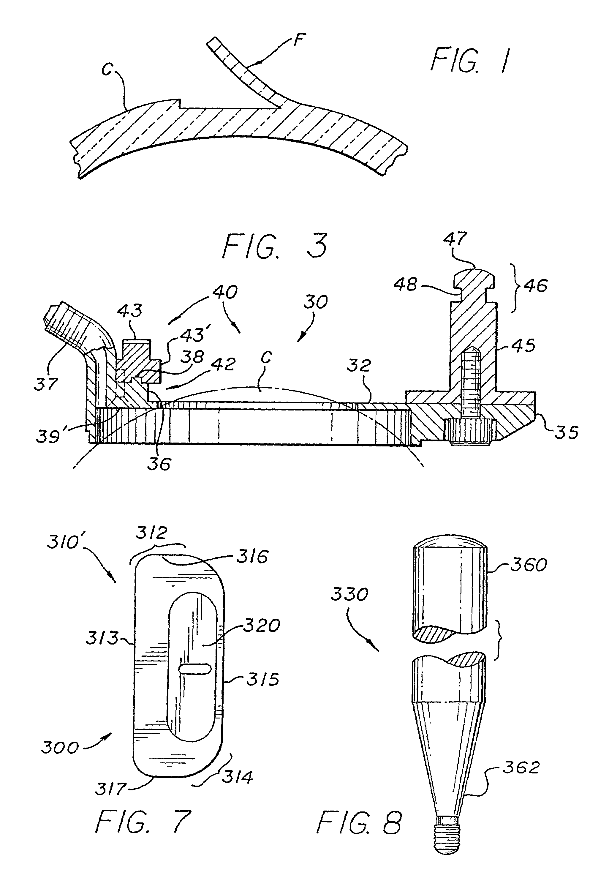
[0038]The preferred and improved automatic microkeratome device of the present invention, which is structured to cut substantially but not completely across the cornea of a patient's eye so as to raise a thin layer thereof and create a hinged flap of corneal tissue, will be discussed first. As illustrated in FIGS. 2 and 3, the preferred microkeratome device 10 includes means 30 for retaining and positioning the eye on which surgery is to be performed. The retaining and positioning means 30, which may be made of high grade stainless steel, preferably comprise a positioning ring 32 having an ape...


PUM


Abstract

A surgical device for cutting substantially across a cornea of an eye of a patient, the device including a positioning ring to be attached to an eye surrounding a cornea to be cut, and defining an aperture sized to receive and expose the cornea to be cut. The surgical device further includes a cutting head assembly structured to be guided and driven over an upper surface of the positioning ring in a generally arcuate path, and having a cutting element positioned therein and structured to oscillate laterally to facilitate smooth and effective cutting of the cornea. The cutting head assembly is structured to be detachably coupled to the positioning ring by a coupling member which permits movement of the cutting head assembly relative to the positioning ring along the generally arcuate path, but maintains sufficient engagement therebetween to ensure that smooth, steady, driven movement is maintained.

Description

[0001]The present application is a continuation-in-part of and claims priority to the following applications and / or issued patents, each of which is incorporated fully herein by reference: U.S. patent application having Ser. No. 09 / 841,165 filed Apr. 24, 2001, now abandoned which is a continuation of an earlier filed U.S. patent application, namely Ser. No. 08 / 840,430 filed on Apr. 29, 1997 which matured into U.S. Pat. No. 6,296,649 on Oct. 2, 2001, which itself was a continuing application based on that U.S. patent application filed on Feb. 7, 1996 and assigned Ser. No. 08 / 598,180 which matured into U.S. Pat. No. 5,624,456 on Apr. 29, 1997. The present application also claims priority to and is a continuation-in-part of the following, each also incorporated fully herein by reference: a U.S. patent application filed on Apr. 24, 1998 and assigned Ser. No. 09 / 065,848 which matured into U.S. Pat. No. 6,007,553 on Dec. 28, 1999, which itself was a Continuation-In-Part application of an ...

Claims


Application Information

Patent Timeline
IPC IPC(8): A61B17/32A61F9/013
CPCA61F9/013A61B19/50A61F2009/0052A61B34/10
Inventor HELLENKAMP, JOHANN F.
Owner HELLENKAMP JOHANN F
Why Eureka
Try Eureka