
Sealed coaxial cable connector and related method

a coaxial cable and connector technology, applied in the direction of couplings/cases, coupling device connections, securing/insulating coupling contact members, etc., can solve the problems of reducing signal strength, affecting performance, and infiltration of moisture into the interior of the connector and into the cabl

Inactive Publication Date: 2004-09-14
PPC BROADBAND INC
View PDF53 Cites 160 Cited by
  • Summary
  • Abstract
  • Description
  • Claims
  • Application Information

AI Technical Summary

Benefits of technology

Accordingly, an object of this invention is to provide connectors and related methods wherein a suitable environmental seal is provided to limit or prevent in ingress of moisture into the interior of the cable.
Another object of the invention is to provide connectors and methods that can be made and used economically.
The body member preferably comprises an annular shoulder integrally connecting the proximal body section and the distal body section to one another, with the collar disposed between the lip and the annular shoulder. In this embodiment, the lip and the annular shoulder are preferably spaced apart by a sufficient distance to permit limited axial movement of the collar of the coupler therebetween before the coupler is engaged with the terminal. The limited axial movement avoids significant engagement of the collar with the lip and permits free-spinning movement of the coupler relative to both the post and the body member until the coupler is tightened onto the terminal.
According to any variation of the fourth embodiment, the body member further comprises an annular shoulder integrally connecting the proximal body section and the distal body section to one another, so that the collar may be situated between the lip and the annular shoulder. The lip preferably has a forward chamfer for facilitating the inserting step (c). The lip and the annular shoulder are preferably spaced apart from one another by a sufficient distance to permit limited axial movement of the collar between the lip and the annular shoulder before the coupler is engaged with the terminal. The limited axial movement avoids significant engagement of the collar with the lip and permits free-spinning movement of the coupler relative to both the post and the body member until the coupler is engaged with the terminal.
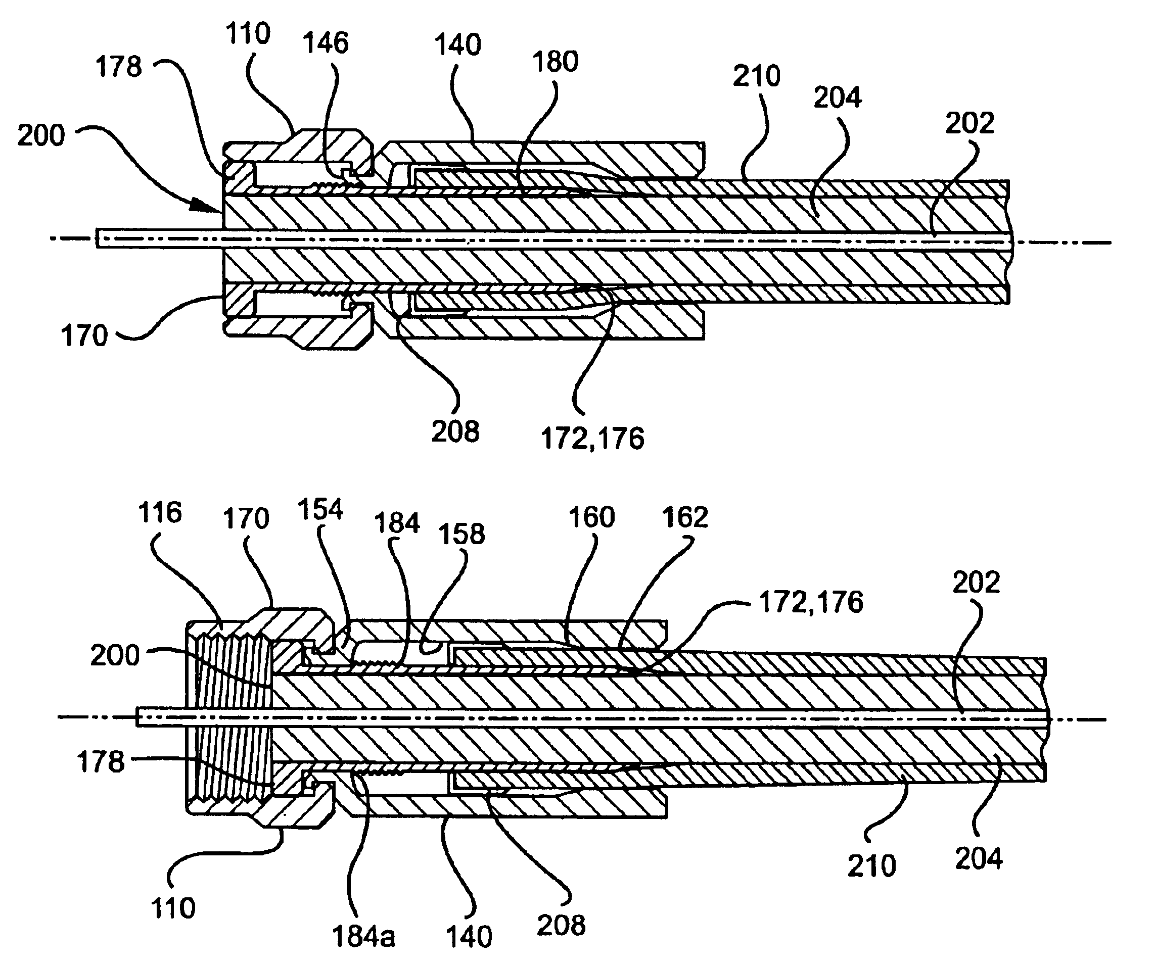
As the coaxial cable is passed into the body member, the post flange preferably is maintained axially spaced apart from the annular collar. The post shank preferably has an outer surface comprising at least one barb or a plurality of barbs. As the post shaft is moved per step (f), the barb traps the outer conductor and the jacket of the coaxial cable. In the event that the body member comprises an annular shoulder integrally connecting proximal and distal body sections of the body member, the barb against the distal shoulder end to prevent forward movement of the post relative to the distal shoulder end.
In a preferred modification to the sixth aspect, the body member further comprises an annular shoulder integrally connecting the proximal body section and the distal body section to one another, and the (c) inserting comprises situating the collar between the lip and the annular shoulder. The lip may optionally have a forward chamfer for facilitating insertion of the lip through the annular collar. The lip and the annular shoulder may be spaced apart by a sufficient distance to permit limited axial movement of the collar between the lip and the annular shoulder before the coupler is tightened to the terminal. The limited axial movement avoids significant engagement of the collar with the lip and permits free-spinning movement of the coupler relative to both the post and the body member until the coupler is engaged with the terminal.

Problems solved by technology

A problem with prior coaxial cable designs, particularly in outdoor applications, has involved unwanted infiltration of moisture at the connector and into the interior of the cable.
This can impair performance, for example, by leading to corrosion, affecting the electrical characteristics within the cable, increasing contact resistance, reducing signal strength, causing excessive RF leakage from the connector, etc.
During assembly, the compression sleeve can easily become lost because of its typically small size and because it must be detachable from a mounting neck.
In addition, such "SNAP-N-SEAL" connectors are significantly more expensive than conventional crimp style connectors.
In some situations, the connector shown in the Hayward '274 patent can not be installed quickly, as by a simple crimp or compression tool.
The need for these various components results in added relative cost of the components themselves, as well as the costs associated with maintaining parts inventories, assembly time and effort, installation time and effort, etc.

Method used


Image

  • Sealed coaxial cable connector and related method
  • Sealed coaxial cable connector and related method
  • Sealed coaxial cable connector and related method

Examples


Embodiment Construction

Reference will now be made in detail to the presently preferred embodiments and methods of the invention as illustrated in the accompanying drawings, in which like reference characters designate like or corresponding parts throughout the drawings. It should be noted, however, that the invention in its broader aspects is not limited to the specific details, representative devices and methods, and illustrative examples shown and described in this section in connection with the preferred embodiments and methods. The invention according to its various aspects is particularly pointed out and distinctly claimed in the attached claims read in view of this specification, and appropriate equivalents.

It is to be noted that, as used in the specification and the appended claims, the singular forms "a," "an," and "the" may include plural referents unless the context clearly dictates otherwise.

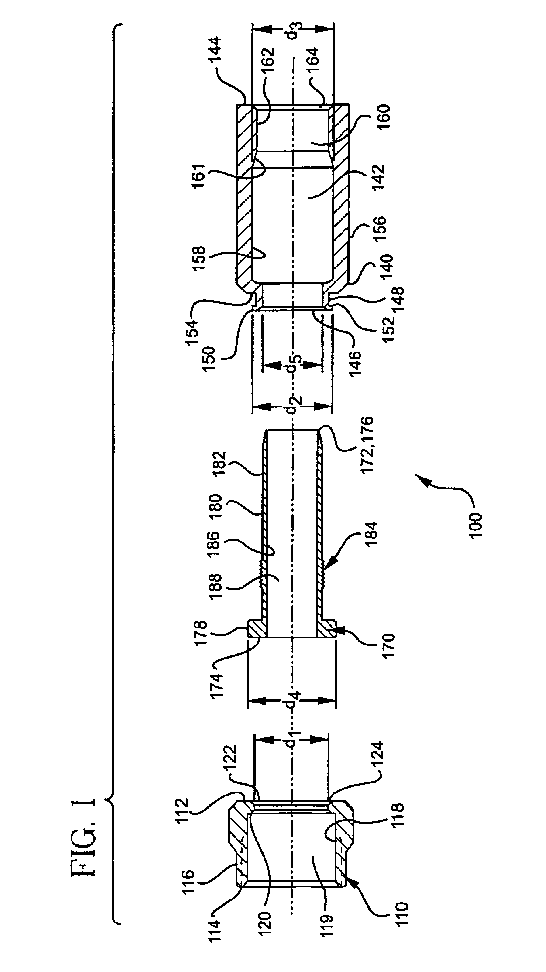
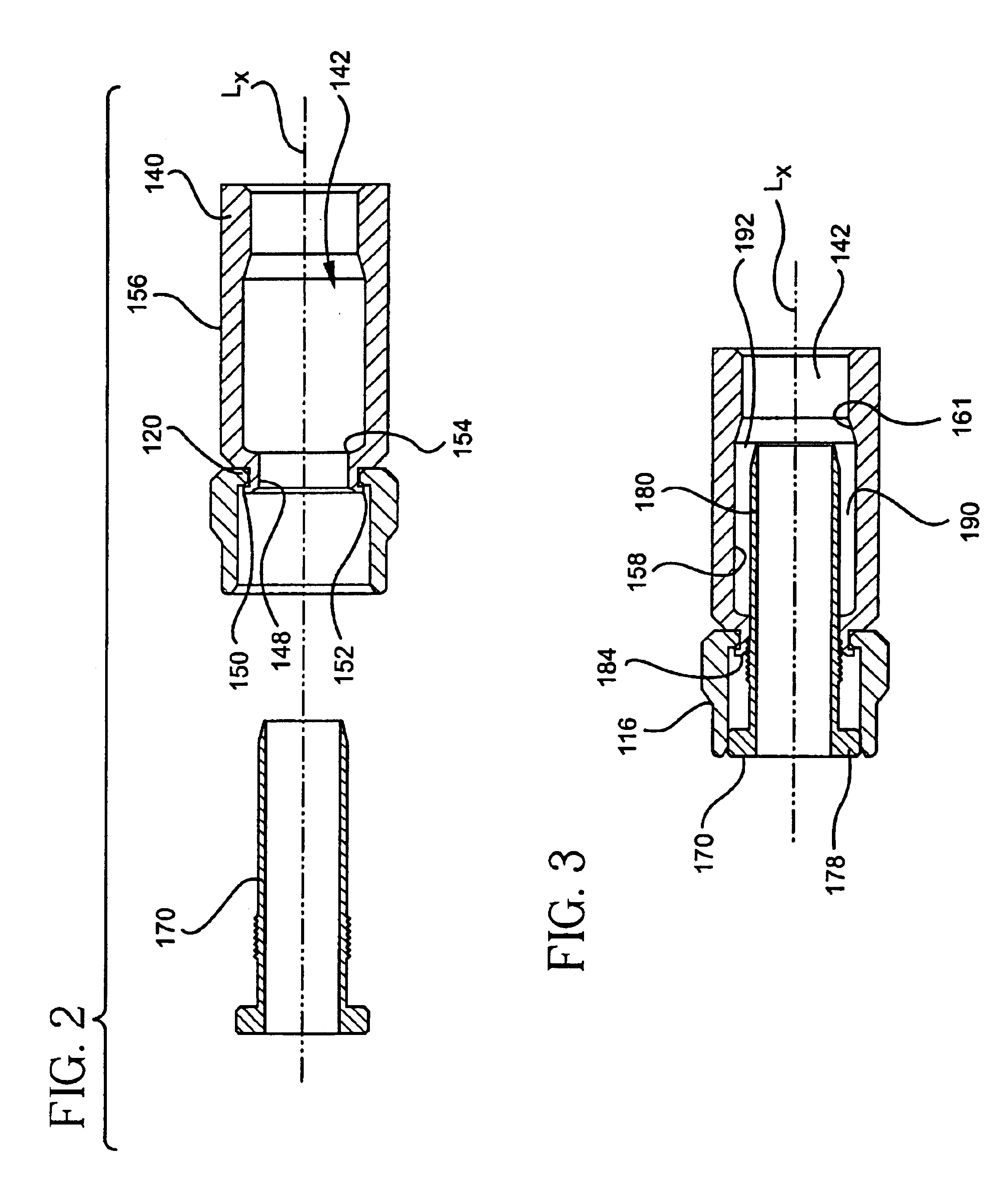
FIGS. 1-3 and 5-7 illustrate an example of a connector, generally designated by reference numeral 100, a...


PUM


Abstract

A coaxial cable connector includes a coupler, a post and a body member. One end of the body member includes a lip that is inserted through the opening in an annular collar of the coupler. In a cable-installed position, the shank of the post is received in the body member to form an annular chamber which is sufficiently narrow to compress the outer conductor and the jacket of a coaxial cable to establish a distal seal. Tightening of the coupler to the terminal compresses the lip between the flange of the post and the annular collar for establishing a proximal seal. Related methods also are provided.

Description

1. Field of the InventionThe present invention relates generally to connectors for coupling cables to terminals, or to one another, etc., and methods for assembling and using the same. More specifically, the invention relates to connectors for coaxial cables and related methods, wherein the connector can provide an environmental sealing role.2. Description of Related ArtThere are many applications in which it is advantageous to connect a coaxial cable to a terminal, another coaxial cable, and the like. Coaxial cable F-connectors, for example, are often used to terminate coaxial cables, such as a drop cable in a cable television system. Such coaxial cables typically include a center or inner conductor surrounded by a dielectric or core, in turn surrounded by an outer conductor or braid, which in turn is surrounded by an outer insulator referred to as a jacket. The F-connector is secured over the prepared end of the jacketed coaxial cable, allowing the end of the coaxial cable to be t...

Claims


Application Information

Patent Timeline
Patent Type & Authority Patents(United States)
IPC IPC(8): H01R9/05H01R13/52H01R3/00H01R24/28H01R24/38
CPCH01R9/0521H01R13/5205H01R9/05H01R13/52H01R13/40
Inventor BURRIS, DONALD A.DURST, HERMAN P.KEARSEY, DAVID M.LUTZ, WILLIAM B.SUNDVOLD, STEVEN E.WOOD, KENNETH S.
Owner PPC BROADBAND INC
Learn More