
Locking device with convertible shank including locking method thereof

a technology of locking device and convertible shank, which is applied in the direction of locks, screw applications, washers, etc., can solve the problems of inconvenient and cumbersome use, inconvenient use of locks, and compounding inconvenience and difficulty of threaded lock systems, etc., and achieves strong mechanical construction and simple construction.

Inactive Publication Date: 2007-01-23
WYERS PHILIP W
View PDF33 Cites 23 Cited by
  • Summary
  • Abstract
  • Description
  • Claims
  • Application Information

AI Technical Summary

Benefits of technology

[0009]It is an object of the present invention to provide a new and useful locking device and method that is simple in construction yet which provides a strong mechanical construction.
[0011]It is yet another object of the present invention to provide a convertible locking structure and method which is adaptable in size for different connection openings.
[0013]A further object of the present invention is to provide a bolt-type locking structure having a pleasing, symmetrical appearance.

Problems solved by technology

The bulky nature of this lock head design, however, makes it disadvantageous in use where only limited space is available.
These types of locks, however, tend to be inconvenient and cumbersome to use due to the threaded nature of their locked mechanisms.
The inconvenience and difficulty of threaded lock systems is compounded when the lock is located in tight or difficult to access areas.
Further, the threaded screw lock is especially prone to corrosion and seizure due to the small dimensioning of the threads.
This is cumbersome and expensive.

Method used


Image

  • Locking device with convertible shank including locking method thereof
  • Locking device with convertible shank including locking method thereof
  • Locking device with convertible shank including locking method thereof

Examples


Embodiment Construction

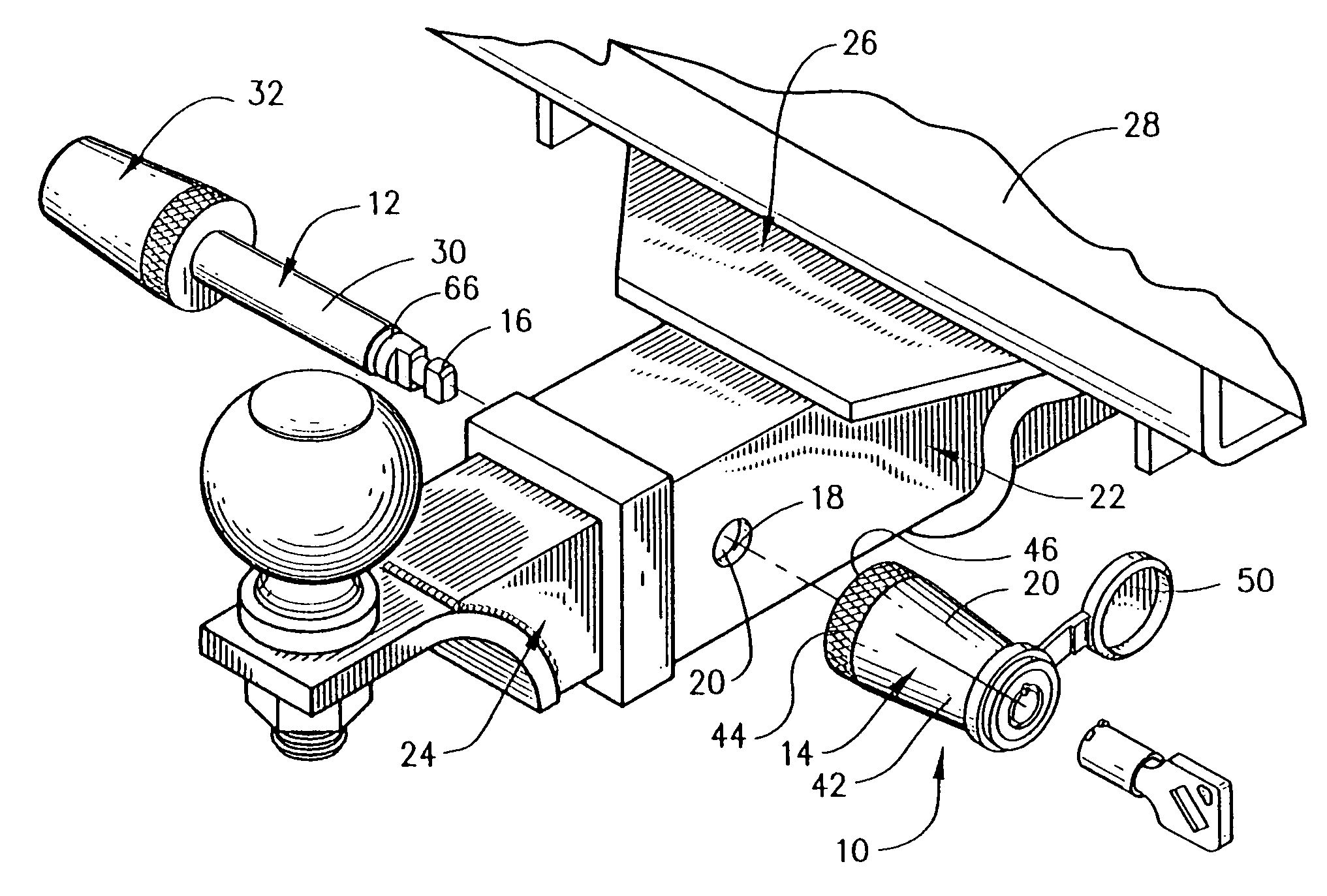
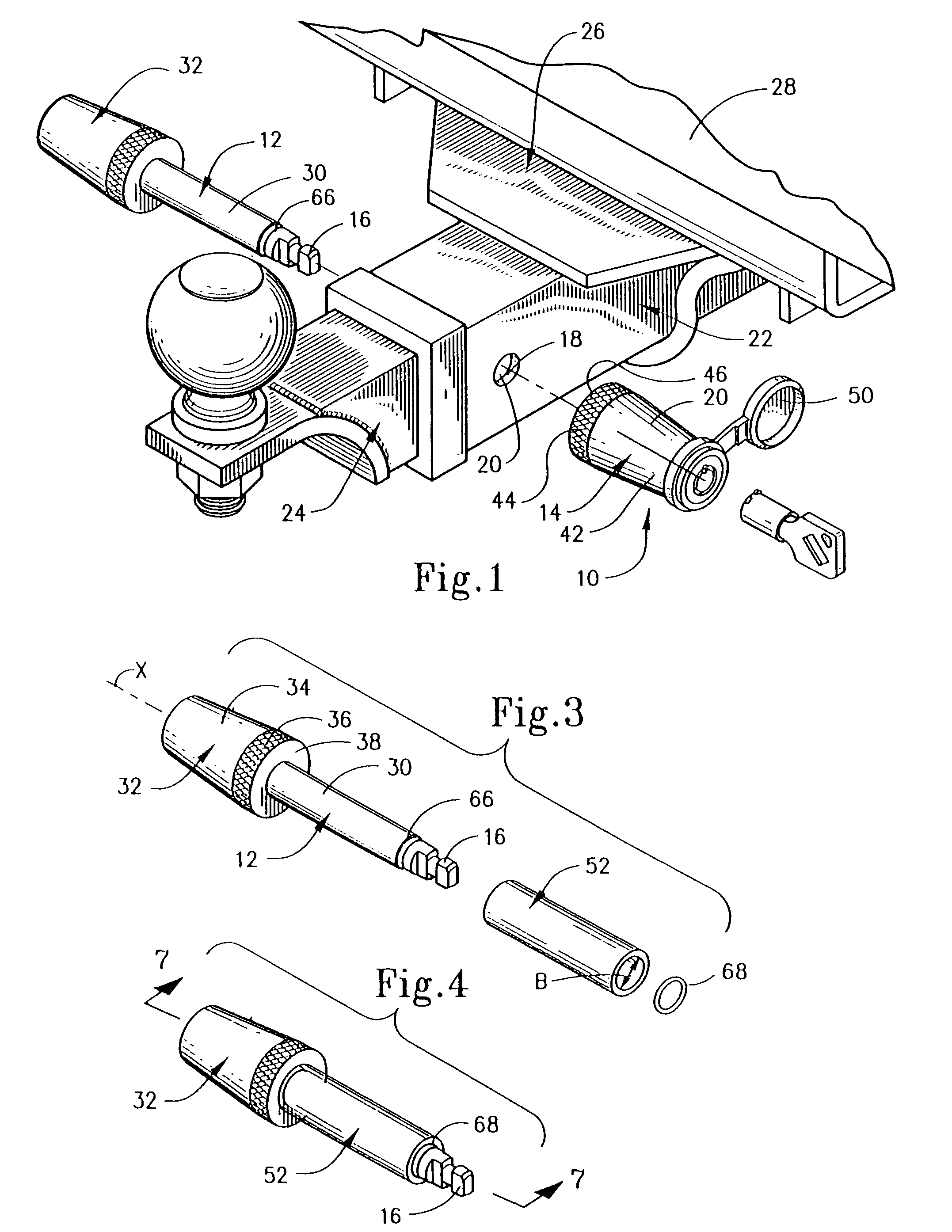
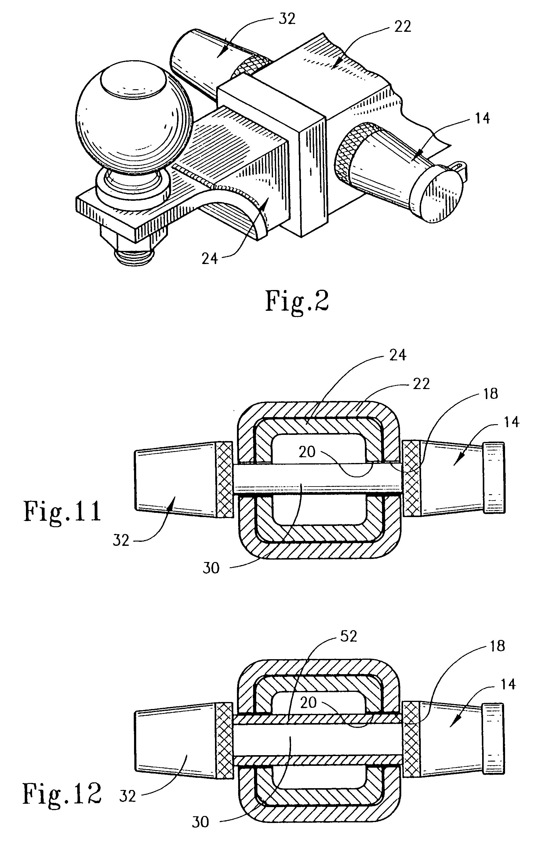
[0040]The present invention is directed to a locking device that is adapted to secure objects together. The locking device is broadly that of my related U.S. patent applications referenced above and preferably includes a key operable locking head that axially mates, through an axial opening thereof, with a shackle member. An axially insertable key rotates a locking core in the locking head in order to rotate a retainer that engages and releases a locking head on a latch portion of the shackle member. While the shackle member may take a variety of configurations, the present invention is particularly useful as a receiver lock that may be employed to secure a draw bar, sometimes also referred to as a hitch barora tow bar, to a trailer hitch receiver. However, the present invention may also be used as a coupler lock, as a watercraft lock, cross bolt gate lock, spare tire lock, bike carrier lock, a cable lock and any other similar locking structure. It should be understood that any numb...


PUM


Abstract

A method utilizes a locking device that includes a shackle member having a shank with a latch portion and a stop at opposite ends. A locking head mounts in a locked state on the latch portion but is removable when unlocked. A sleeve is carried on the shank but is removable. The sleeve and the shank together define a size conversion structure for the shackle. When the sleeve is on the shank, the shackle has one operative thickness to closely fit one size aperture, but when the sleeve is removed, the shackle has another, smaller operative thickness to fit a smaller aperture. A retaining member may be employed to resist removal of the sleeve. Two or more sleeves may be used to fit more than two apertures. These can be separately mountable onto the shank or may be nested on the shank, one inside of the other.

Description

RELATED APPLICATION[0001]This application is a divisional application of U.S. patent application Ser. No. 09 / 556,637, filed Apr. 24, 2000, now U.S. Pat. No. 6,672,115 issued Jan. 6, 2004, which was related to U.S. patent application Ser. No. 09 / 153,511, filed Sep. 15, 1998, the contents of which are specifically incorporated herein and which was further related to U.S. patent application Ser. No. 09 / 153,511, filed Sep. 15, 1998, now U.S. Pat. No. 6,055,832 issued May 2, 2000, the contents of which are specifically incorporated herein.FIELD OF THE INVENTION[0002]The present invention broadly relates to locking devices that are adapted to secure objects together. More particularly, the present invention concerns key operable locking devices. The present invention is directed to size adjustable locking shackles and shanks for such locking devices that, for example, may be used for towage applications, bicycles and the like. This invention specifically includes a method of providing siz...

Claims


Application Information

Patent Timeline
Patent Type & Authority Patents(United States)
IPC IPC(8): E05B67/36B60D1/52B60D1/60E05B35/04E05B63/00
CPCB60D1/52E05B67/36B60D1/60E05B63/0056Y10T70/5982Y10T70/7723Y10T70/443Y10T70/7678Y10T70/7751Y10T70/8838Y10T70/40
Inventor WYERS, PHILIP W.
Owner WYERS PHILIP W
Learn More