
Technique for multiprotocol transport using MPLS (multi-protocol label switching)

a multi-protocol, label switching technology, applied in the direction of data switching networks, digital transmission, electrical equipment, etc., can solve the problems of limited support for multi-protocol transport in mpls, inability to efficiently utilize different paths through the ip network, and difficult task of managing local network routing tables, etc., to achieve more scalable hardware and software solutions, reduce network resources, and reduce costs

Active Publication Date: 2007-01-09
TAIWAN SEMICON MFG CO LTD
View PDF11 Cites 37 Cited by
  • Summary
  • Abstract
  • Description
  • Claims
  • Application Information

AI Technical Summary

Benefits of technology

[0011]The objects, features and advantages of the present invention include providing a router and method that may provide for (i) sending multiple protocols / flows simultaneously in a Multi-Protocol Label Switching (MPLS) Label Switched Path, (ii) constructing paths for certain Traffic Engineering parameters over a network and / or multiple networks then using each path for multiple types of traffic, (iii) simpler, less expensive, and more scalable hardware and software solutions for devices and networking systems, (iv) consuming fewer network resources to accommodate multi-protocol transport, (v) a capability where network providers can establish network paths for customers independent of the type of data the customers are sending, and / or (vi) no additional hardware and / or software burden on intermediate MPLS nodes for each end system protocol that is to be sent on MPLS paths.

Problems solved by technology

With a large number of nodes and networks, management of the local network routing tables becomes a difficult task, both for hardware and software.
Therefore, even if network bandwidth is available, current protocols are not able to utilize different paths through the IP network efficiently.
A problem, however, is limited support for multiprotocol transport in MPLS.
Another problem arises with signaling protocols such as RSVP where a path needs to be periodically refreshed to keep the path alive.
With many LSPs, a large number of refreshes cause heavy loads on processors and on the network.
The above-mentioned problems have restricted wide adoption of MPLS.
In addition, MPLS systems have been complex and expensive due to additional hardware complexity required for multi-service transport.

Method used


Image

  • Technique for multiprotocol transport using MPLS (multi-protocol label switching)
  • Technique for multiprotocol transport using MPLS (multi-protocol label switching)
  • Technique for multiprotocol transport using MPLS (multi-protocol label switching)

Examples


Embodiment Construction

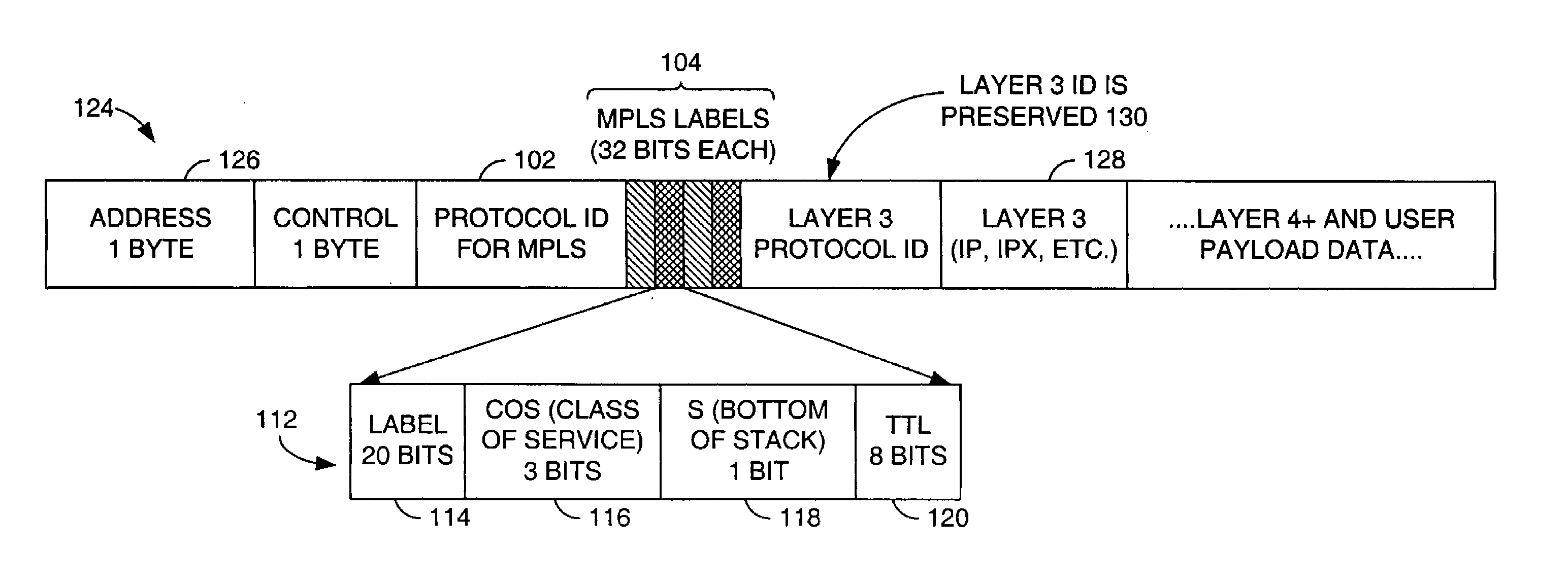
[0021]Referring to FIG. 3, a drawing is shown of an Ethernet frame in a Multi-Protocol Label Switching (MPLS) protocol 100 in accordance with a preferred embodiment of the present invention. The MPLS protocol is generally defined in the document, “Multiprotocol Label Switching Architecture”, Internet Engineering Task Force (IETF), Reston Va., Request For Comment (RFC) 3031, hereby incorporated by reference in its entirety. The MPLS protocol is generally modified by the present invention.

[0022]Modifying the Ethernet frame for the MPLS generally comprises adding a field 102 and a stack 104 to the Ethernet frame. The field 102 may be implemented as an MPLS protocol identification field as defined by the RFC 3031. The stack 104 may be implemented as an MPLS label stack as defined by the RFC 3031.

[0023]The MPLS protocol identification field 102 and the MPLS label stack 104 may be inserted into the Ethernet frame between a field 106 and a field 108. The field 106 may contain an Open Syste...


PUM


Abstract

A router generally comprising a first port, a second port, and a circuit. The first port may be configured to receive a frame having a network layer protocol identification. The second port may be connectable to a Multi-Protocol Label Switching (MPLS) network. The circuit may be configured to (i) insert an MPLS label into the frame while retaining the network layer protocol identification and (ii) present the frame in the MPLS network per the MPLS label.

Description

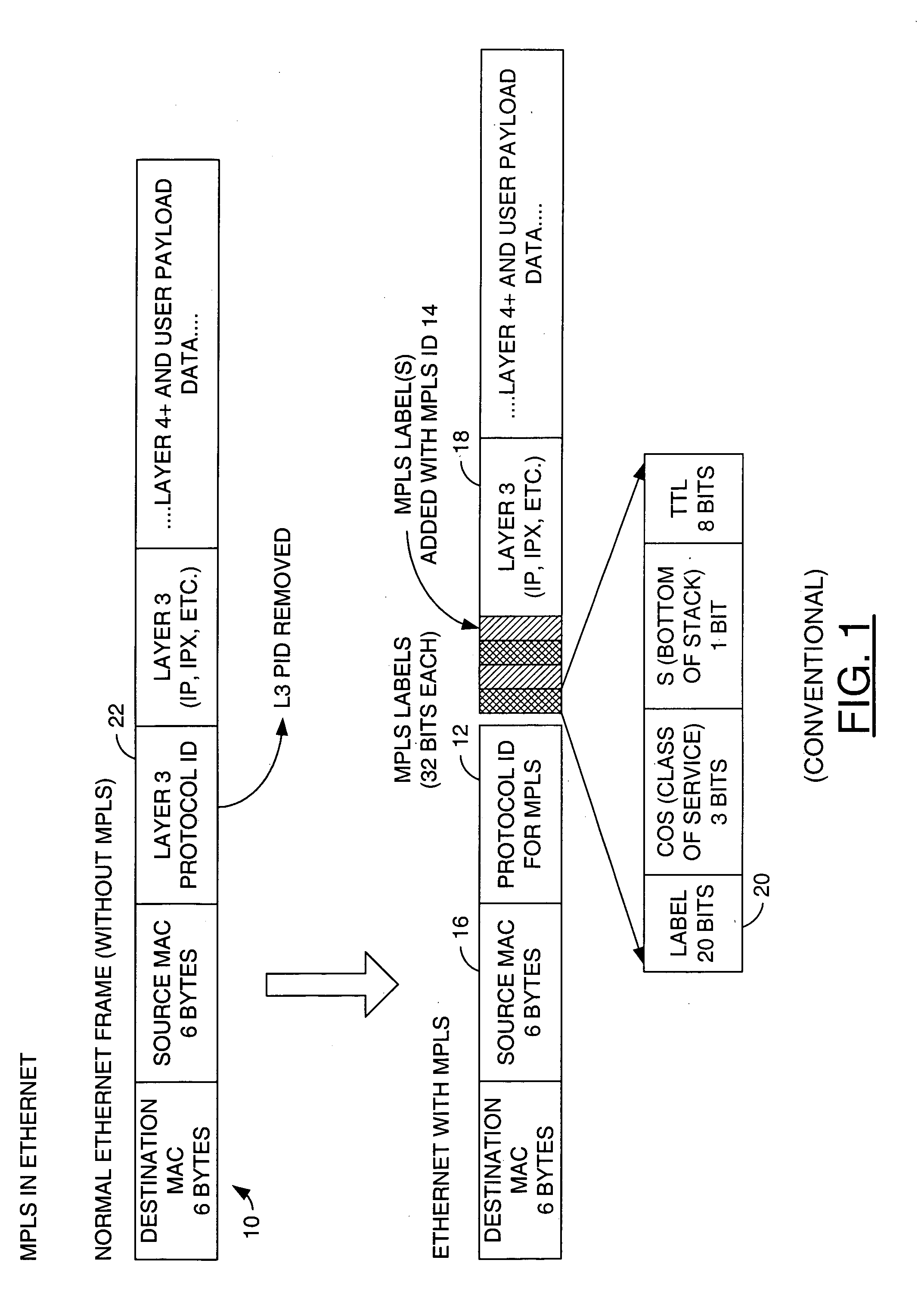
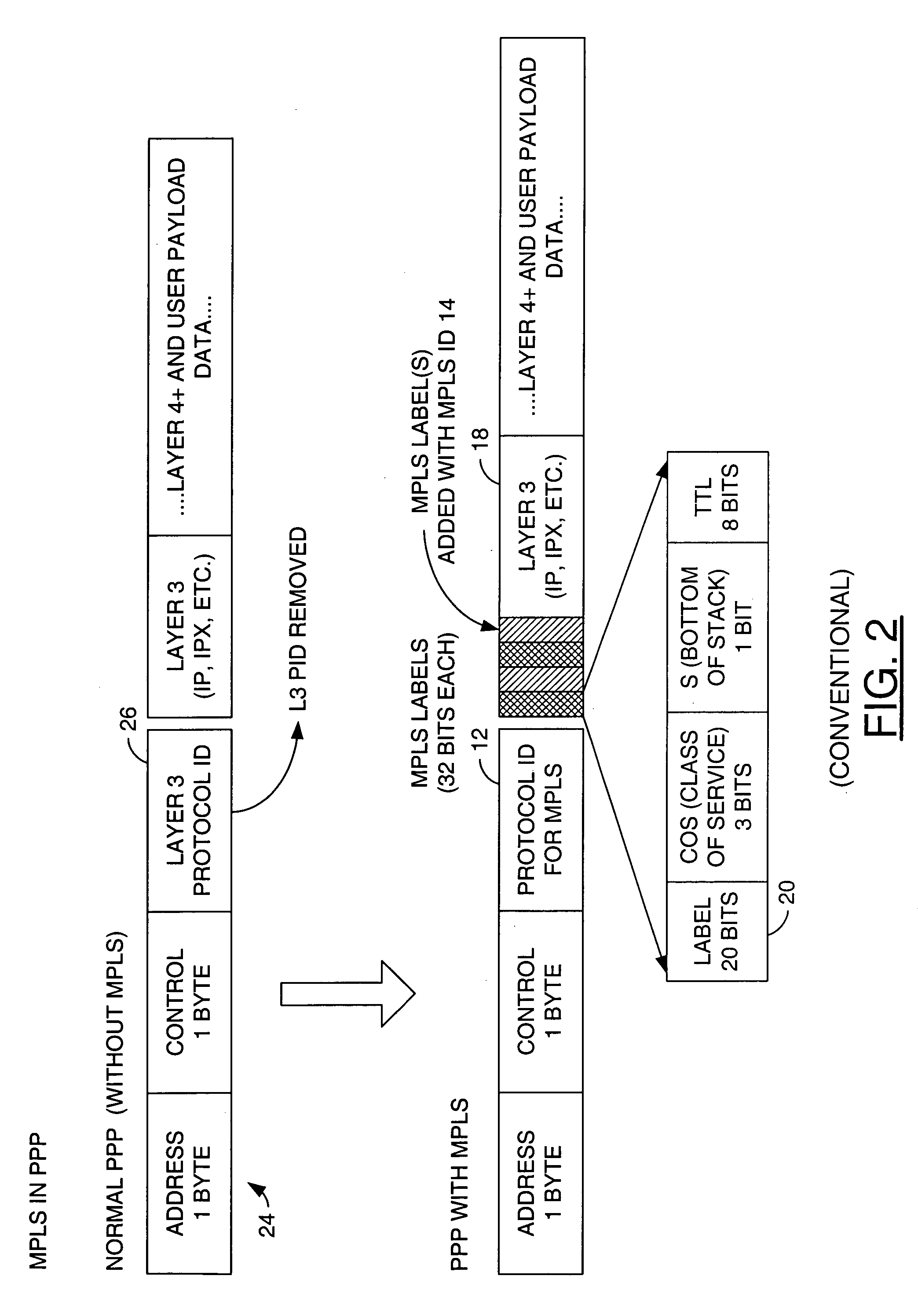
FIELD OF THE INVENTION[0001]The present invention relates to a method and / or architecture for network routing generally and, more particularly, to a router and method for sending multiple protocols over a single pipe within the network.BACKGROUND OF THE INVENTION[0002]Traditional Internet Protocol (IP) based networks require every node to look at network layer values of an Open Systems Interconnection (OSI) model (i.e., IP addresses) within each frame, refer to local network routing databases, and then make decisions about where to forward the frames. With a large number of nodes and networks, management of the local network routing tables becomes a difficult task, both for hardware and software. In addition, current IP networks provide a single routed path between any source and a destination. Therefore, even if network bandwidth is available, current protocols are not able to utilize different paths through the IP network efficiently.[0003]Referring to FIG. 1, a drawing of an Ethe...

Claims


Application Information

Patent Timeline
Patent Type & Authority Patents(United States)
IPC IPC(8): H04L12/28
CPCH04L45/502H04L45/00
Inventor JHA, PANKAJ K.
Owner TAIWAN SEMICON MFG CO LTD
Learn More