
Housing structure of electronic device and heat radiation method therefor

a technology of electronic devices and housings, applied in the field of electronic devices, can solve the problems of no effect, corrosion of electrical circuit components inside the housing, condensation of water inside the housing, etc., and achieve the effect of enhancing the heat radiation effect of the sealed housing and enhancing the reliability of an electronic device operation

Inactive Publication Date: 2007-01-09
NEC CORP
View PDF7 Cites 34 Cited by
  • Summary
  • Abstract
  • Description
  • Claims
  • Application Information

AI Technical Summary

Benefits of technology

[0007]It is an object of the present invention to provide a housing structure of an electronic device and a heat radiation method therefor, which can improve a heat radiation effect of a sealed housing and prevent invasion of water vapor or poisonous gas thereinto from the exterior, thereby to solve the foregoing problems.
[0011]As described above, according to the housing structure of the electronic device and its heat radiation method of the present invention, it is possible to increase the heat radiation effect of the sealed housing and simultaneously prevent an accident caused by dew condensation, corrosion of the electrical circuit component, or the like inside the sealed housing, so that reliability of an operation of the electronic device can be further enhanced.

Problems solved by technology

However, when, for example, the membrane filter is used, if water vapor or poisonous gas invades from the exterior passing through the membrane filter, dew condensation is resulted inside the housing.
Consequently, there has been a problem of occurrence of a phenomenon such as corrosion of electrical circuit components inside the housing.
On the other hand, if the tube containing water is employed for solving it, there has been a problem that no effect is achieved when the water is vaporized.

Method used


Image

  • Housing structure of electronic device and heat radiation method therefor
  • Housing structure of electronic device and heat radiation method therefor
  • Housing structure of electronic device and heat radiation method therefor

Examples


Embodiment Construction

[0020]Preferred embodiments of the present invention will be described below in detail with reference to the drawings.

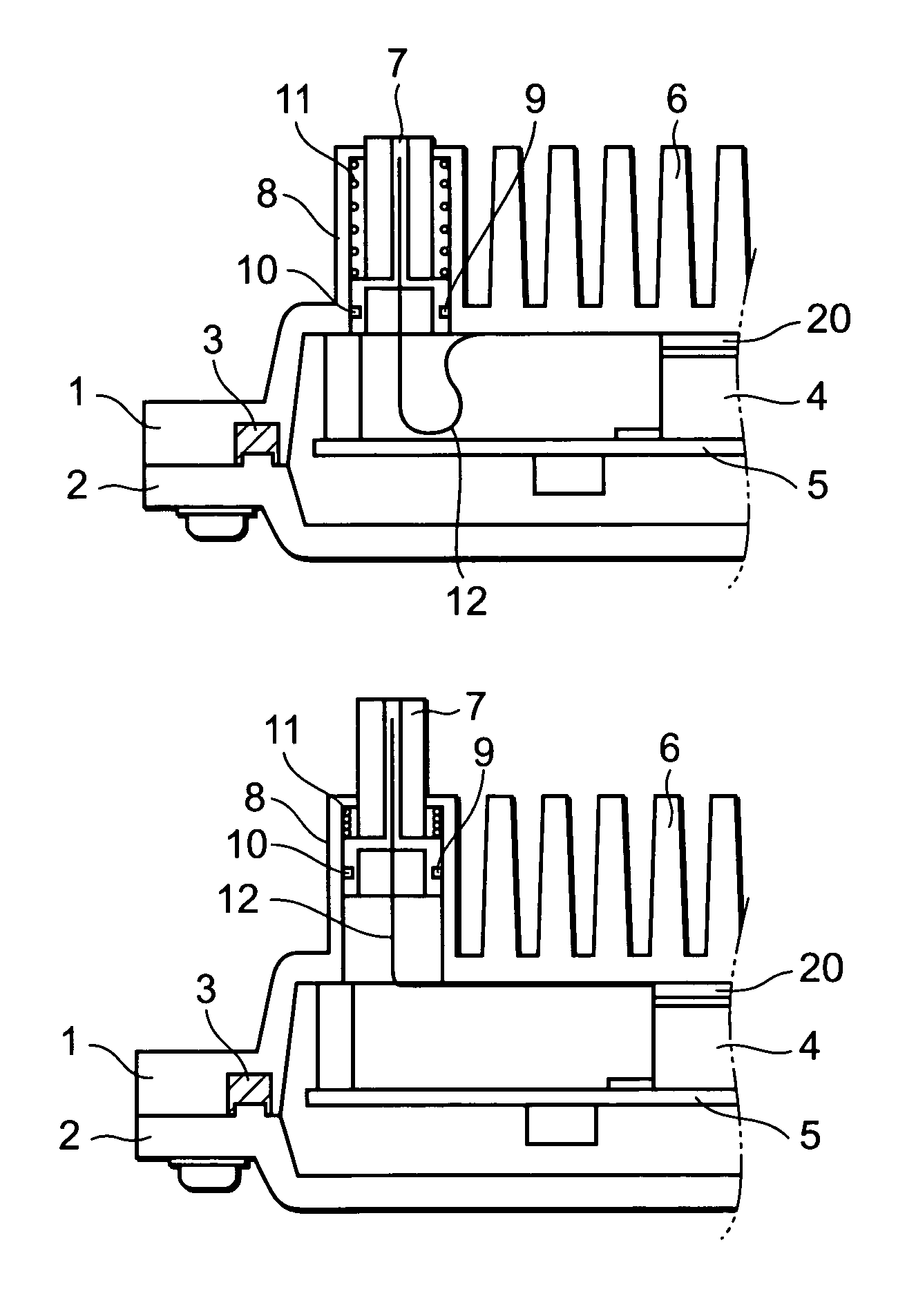
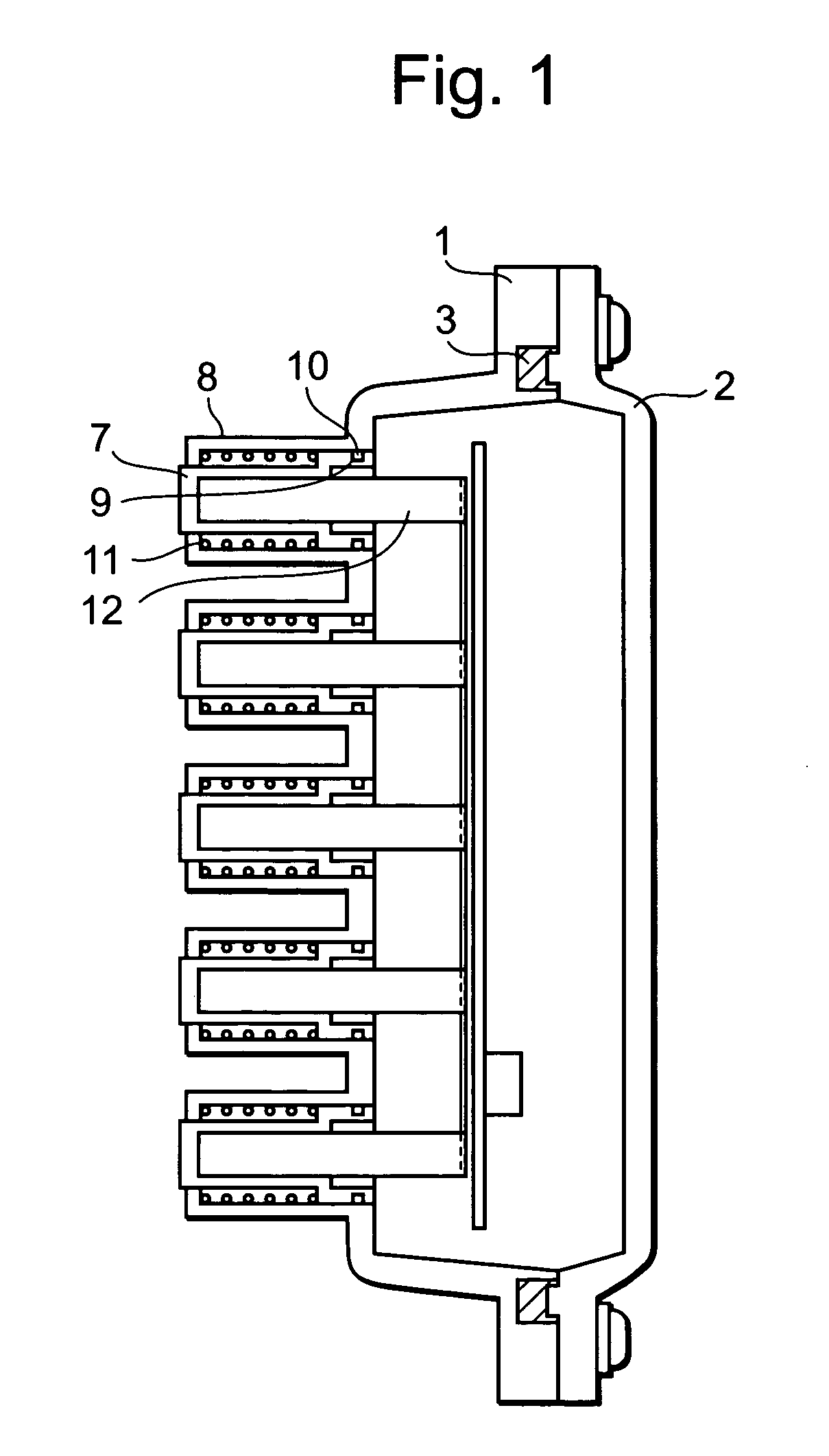
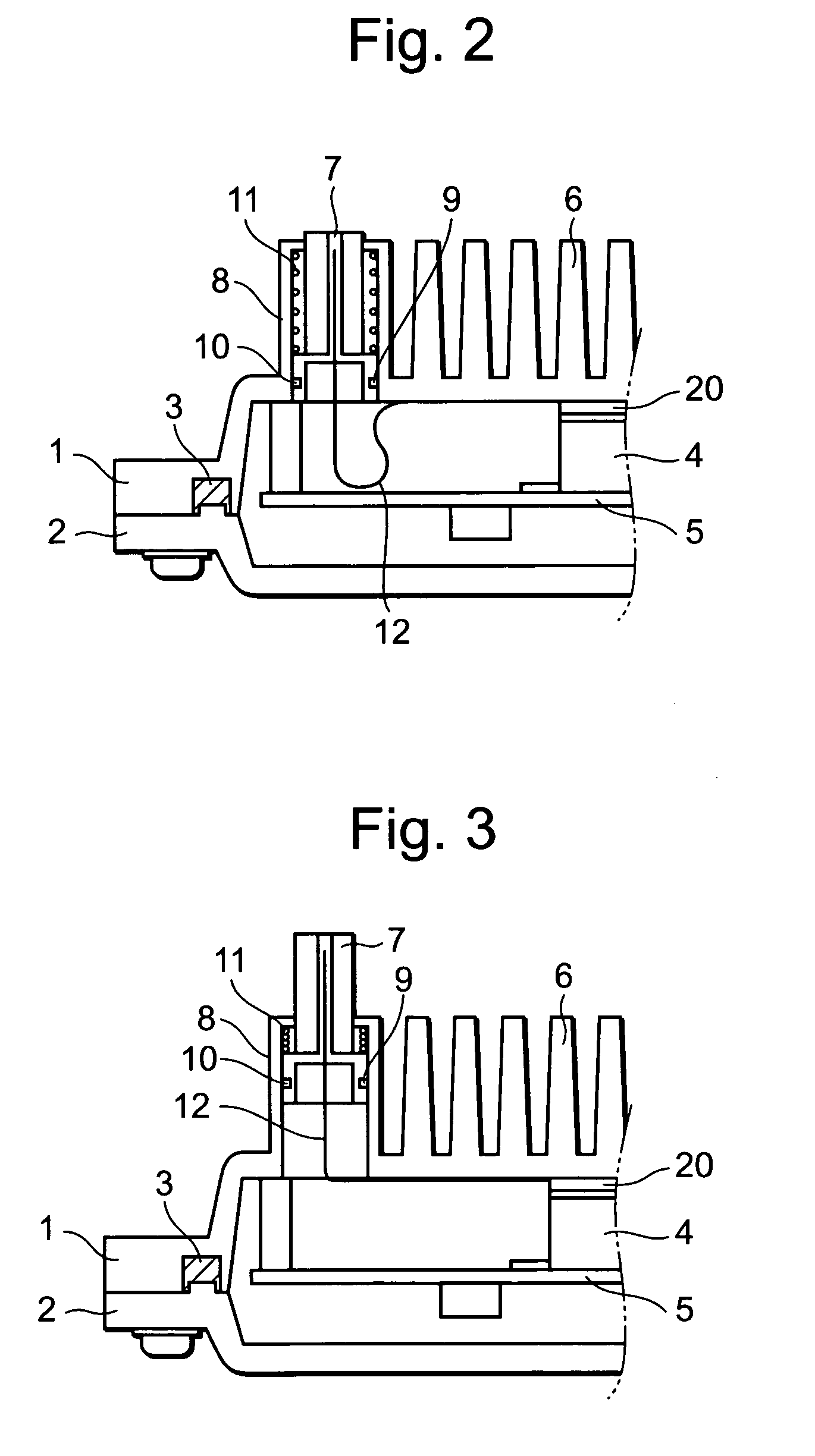
[0021]Sectional views of the first preferred embodiment are shown in FIGS. 1, 2, and 3. FIGS. 2 and 3 each show part of a section view of a portion, in a depth direction thereof, including a movable fin 7 in FIG. 1. A body 1 and a cover 2 are joined together via a packing 3 to form a sealed housing.

[0022]The sealed housing is provided therein with a board 5 attached with a package 4 or the like having electrical circuit components mounted therein.

[0023]In order to radiate heat generated by the electrical circuit components, the package 4 is tightly brought into contact with the inner periphery of heat radiation fins 6 forming part of the inner periphery of the body 1, via a heat conductive member 20.

[0024]The body 1 is provided with guide portions 8, and it is configured that the movable fin 7 in each guide portion 8 is smoothly guided by the guide portion 8 to slide...


PUM


Abstract

A sealed housing is provided with a body, a cover, and a movable fin for radiating heat while suppressing a change in internal pressure, and preventing invasion of water vapor or poisonous gas from the exterior to thereby avoid an accident caused by dew condensation, and corrosion of an electrical circuit component. The movable fin automatically slides toward the inside or outside of the sealed housing depending on a change in internal atmospheric pressure of the sealed housing following a change in internal temperature thereof. When the temperature inside the sealed housing rises due to heat from the electrical circuit component mounted in a package inside the sealed housing, a heat radiation area of the movable fin increases while keeping sealing tightness so that a heat radiation effect can be enhanced.

Description

BACKGROUND OF THE INVENTION[0001]1. Field of the Invention[0002]The present invention relates to an electronic device such as a communication device and, in particular, relates to a housing structure of an electronic device having a sealed housing, and further to a heat radiation method therefor.[0003]2. Description of the Related Art[0004]With respect to a sealed housing used in an electronic device such as a communication device, a rise in temperature inside the housing is induced by heat generation from electrical circuit components mounted in a package or the like inside the housing, or due to a change in external environment. In order to suppress the rise in temperature to enhance reliability of an operation of the electronic device, the conventional sealed housing is provided with a heat radiation structure such as fins on the outer periphery of the housing. The heat radiation capacity of the housing is determined by a heat radiation effect of the heat radiation structure, and...

Claims


Application Information

Patent Timeline
IPC IPC(8): H05K7/20F28F7/00H01L23/34H05K5/02H01L23/40H05K5/06
CPCH05K5/061H05K7/20409H05K5/068
Inventor OYAMADA, TAKASHI
Owner NEC CORP
Learn More