
Modifying the electro-mechanical behavior of devices

a technology of electromechanical behavior and device, which is applied in the direction of coupling device connection, electrical apparatus casing/cabinet/drawer, instruments, etc., can solve the problems of increasing performance, reducing the cost of devices, and increasing the complexity of manufacturing processes

Inactive Publication Date: 2007-01-09
SNAPTRACK
View PDF295 Cites 62 Cited by
  • Summary
  • Abstract
  • Description
  • Claims
  • Application Information

AI Technical Summary

Problems solved by technology

The process of hermetically sealing packages contributes to the cost of the devices, as well as the complexity of the manufacturing process.
High humidity may cause problems with stiction, a combination of sticking and friction, while completely dry environments may have other effects.
Other aspects of the environment may cause problems or result in increased performance.

Method used


Image

  • Modifying the electro-mechanical behavior of devices
  • Modifying the electro-mechanical behavior of devices
  • Modifying the electro-mechanical behavior of devices

Examples


Embodiment Construction

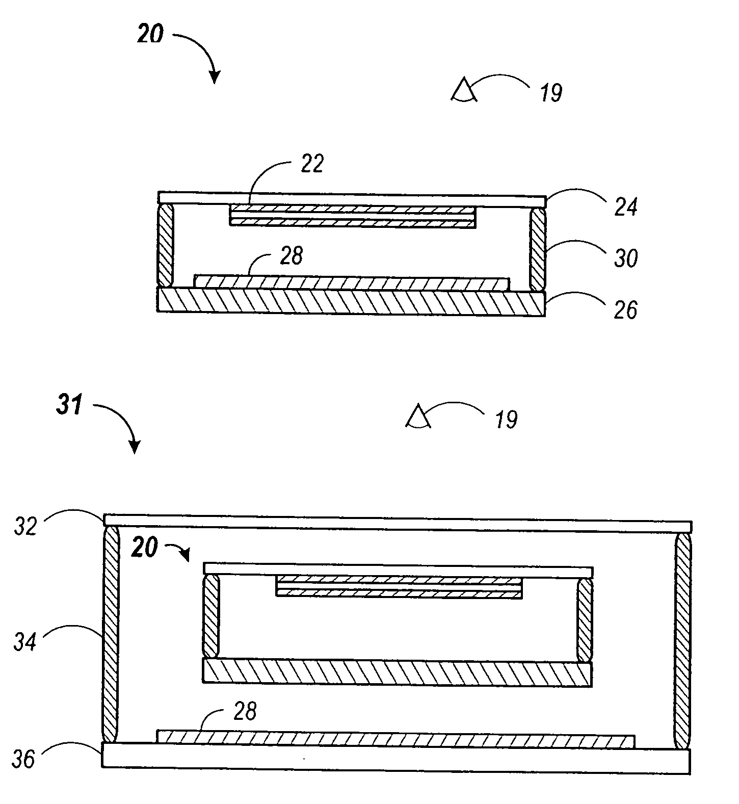
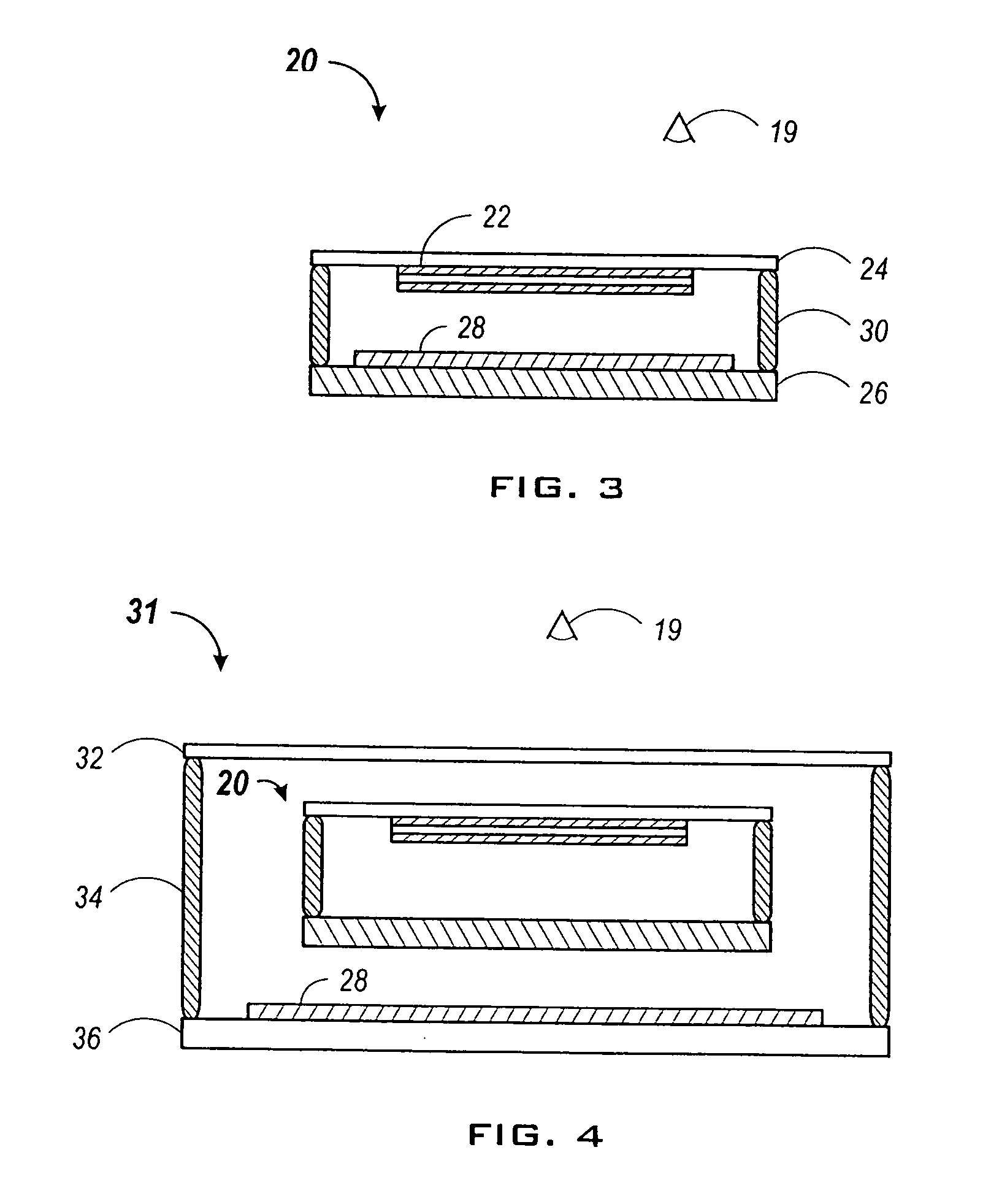
[0015]Microelectromechanical (MEMS) devices include a large class of devices in which mechanical structures come into contact with other structures of a different material. For example, a movable element may contact a surface coated with dielectric. The presence of moisture in these types of MEMS devices may result in altered behaviors that may or may not be desirable.

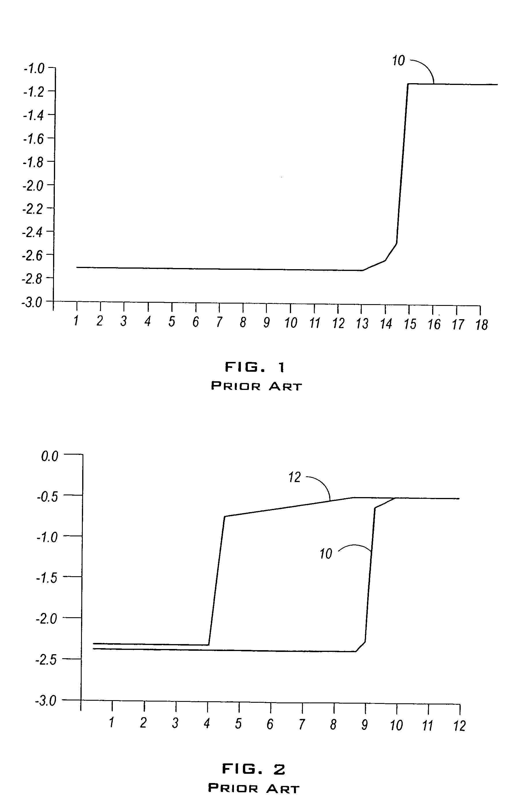
[0016]An example of an undesired behavior occurs when humidity in the device operating environment becomes too high. When the humidity level exceeds a level beyond which surface tension from the moisture becomes higher than the restoration force of a movable element, the movable element may become permanently stuck to the surface. If the humidity level is too low, the moisture charges up to the same polarity as the movable element when the element comes into contact with the coated surface. This may cause a collapse of the hysteresis curve 10 shown in FIG. 1. FIG. 1 shows a typical operating curve for a MEMS device in ...


PUM


Abstract

A MEMS device is packaged with a control material that is included in the package to affect an operation of a moveable element of the device. The control material may affect operational characteristics including actuation and release voltages and currents, mechanical affects including damping and stiffness, lifetime of the device, optical properties, thermal affects and corrosion. The control material may be inserted into the package as part of any of several structural components of the package or the MEMS device.

Description

CROSS REFERENCE TO RELATED APPLICATIONS[0001]This application is a continuation of, and claims priority to, U.S. patent application Ser. No. 10 / 839,307, filed May 4, 2004 now U.S. Pat. No. 7,060,895, which is incorporated by reference in its entirety.BACKGROUND OF THE INVENTION[0002]Microelectromechanical systems (MEMS) typically involve at least one movable element in a self-contained package. For example, spatial light modulators such as interferometric or deflectable, reflective modulators may be contained in a package having a clear window offset from a substrate by a ring or other packaging support. MEMS-based switches may be encased in packages having protective caps offset from a substrate by similar components. Generally, MEMS devices will lie between the substrate and an offset cap or cover, as the devices need room to move when activated by an actuation signal.[0003]This packaging type results in an operating environment for the MEMS devices that needs to be controlled. In...

Claims


Application Information

Patent Timeline
Patent Type & Authority Patents(United States)
IPC IPC(8): H01L23/18B81B7/00G02B26/00
CPCG02B26/001B81B7/0038
Inventor KOTHARI, MANISHCHUI, CLARENCEPALMATEER, LAUREN
Owner SNAPTRACK
Learn More