
System and method for efficient and low energy desalination of water

a technology of water desalination system and low energy, applied in the field of desalination of water, can solve the problems of more waste of energy and high construction cost of such conduits, and achieve the effects of less mechanical problems, easy cleaning, and less waste of energy

Inactive Publication Date: 2007-01-09
BARHON MAYER BATYA +1
View PDF11 Cites 13 Cited by
  • Summary
  • Abstract
  • Description
  • Claims
  • Application Information

AI Technical Summary

Benefits of technology

[0018]The present invention tries to solve the above described problems by using a process that is even simpler and has less mechanical problems, and therefore can be even more energy efficient. There are a number of possible solutions: 1. A better solution is to use, instead of nozzles, holes in a water container, preferably for example with a container shaped like a cylinder or a ball. This is much better since there is much smaller danger of the holes getting clogged, and it is also much easier to clean them, and also this way the water droplets can fly in all desired directions instead of vertically. 2. Another possible solution is to use for example gravitational forces instead of a water pump. So in Israel for example water can be brought from the Mediterranean Sea and dropped down for example above the Dead sea into a water conductor that has holes in the appropriate depth and sizes to allow the water to fly out at the desired speeds. However, building such a conduit is expensive and can be used only at a small number of places in the world. 3. A still better solution is, to use instead of a water pump or pressure, centrifugal forces, which are more efficient since they are applied directly to throwing out the water droplets, with or without holes. However many improvements are shown also over the rotating cup described by Secunda at. al., which can allow much more control on the droplets size and speed, allow better separation of the water and the salt, and try to solve the above problem of contradicting parameters requirements for water with low concentrations of salt, such as for example sea water. This is the more preferred solution in the present invention.
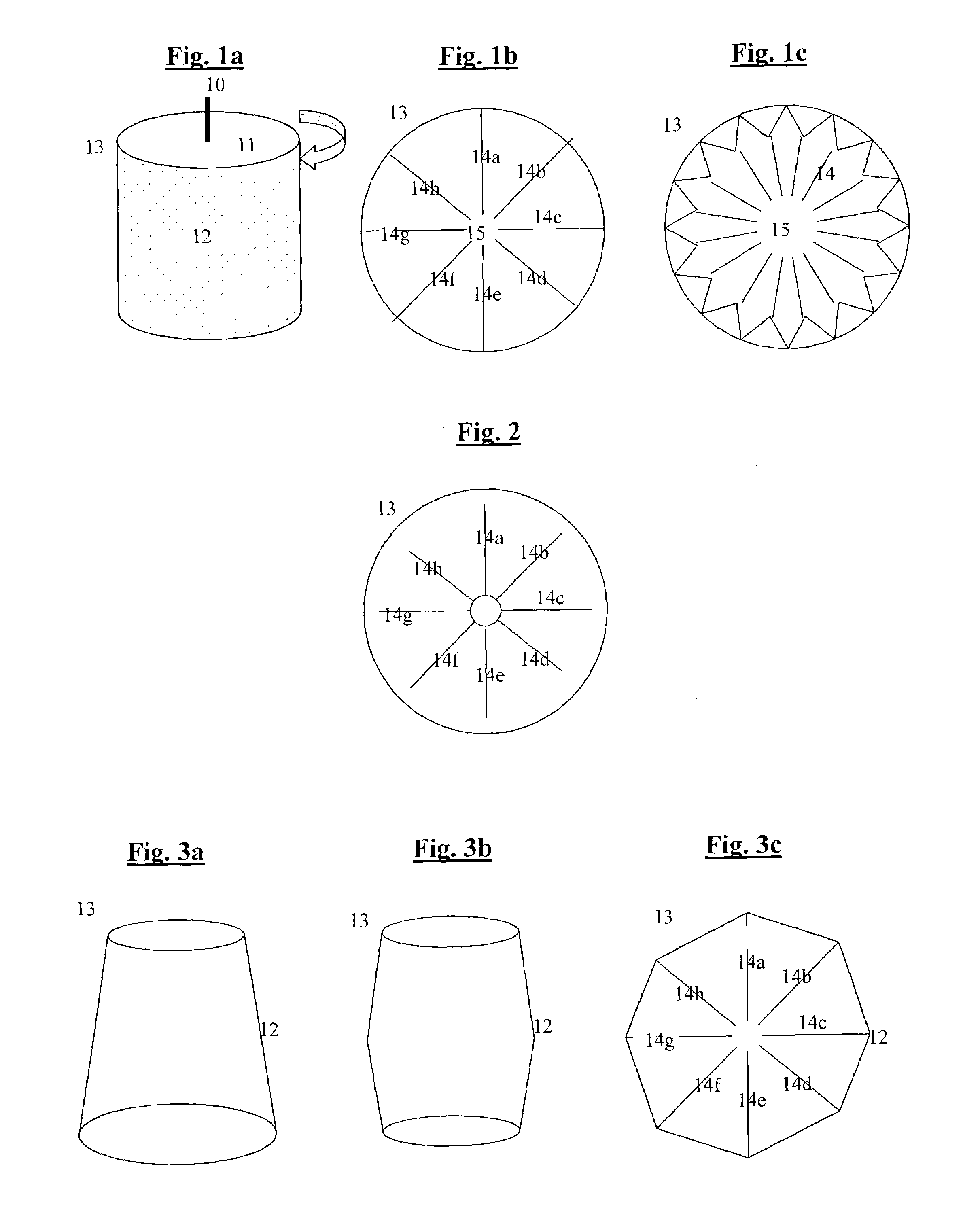
[0021]Another possible variation, shown in FIG. 2, is to independently rotate the cells themselves, or parts of them, or other elements, instead or in addition to the rotation of the cylinder itself, thus adding to the effect of throwing out the droplets also throwing out water already in the form of steam, created by cavitation. Another possible variation is to create a cavitation effect in addition or instead also in the air itself where the droplets are flying, for example by using a propeller or a piston or a rotating wing for intermittently changing between lower and higher pressures.
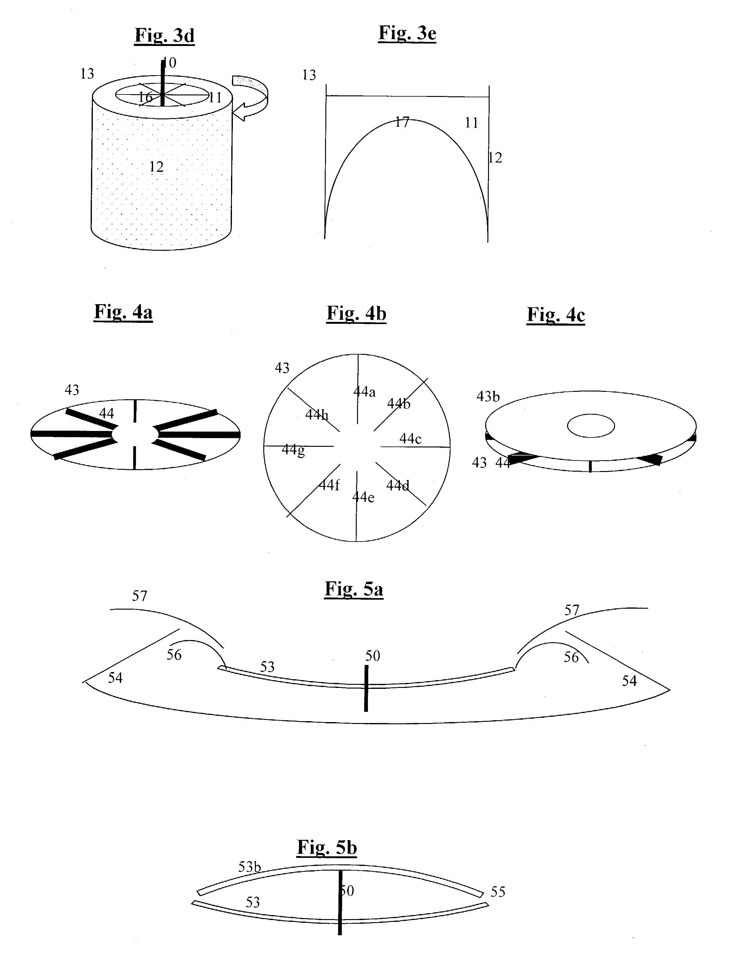
[0023]Another possible variation, shown in FIGS. 4a–c, is to use instead of the cylinder for example a large flat round surface, preferably also separated into cells by vertical walls, so that water is preferably continuously poured on the center of the surface and the centrifugal forces disperse it into small droplets that fly out at the open ends of the cells. Another possible variation is to add for example small teeth at the circumference of the surface in order to further help create the required size of droplets. Another possible variation is to add a top to the surface, so that the vertical walls are between two round surfaces, in order to prevent the water from trying flying upwards to escape the centrifugal forces. Another possible variation, shown in FIG. 5a, is to use a bowl-like surface instead of the flat surface, so that as the water layer gets closer to the periphery it gets thinner and thinner, preferably, close to the thickness of the required droplets size. Another possible variation is to cover this bowl-like surface with a cover, which can be for example a reversed similar upside-down bowl, or a flat surface, as shown in FIG. 5b. Another possible variation is to add a hydrophobic substance at least at the edges or periphery of the bowl-like or flat surface (or at the round walls of the cylinder, in the variations where a cylinder is used), such as for example Teflon, so that the water droplets fly off more easily. On the other hand, hydrophobic materials can cause the water to slip instead of rotating with the object, so preferably most of the rotating body is covered with hydrophilic materials and the hydrophobic materials are preferably only at the extreme edges. The desalination device itself can be used for example at an installation where water is brought from the sea, desalinated, and the waste products are conveyed back to the sea, except that, unlike for example in reversed osmosis, the waste is mainly dry salt, so there is no need to convey back salty water to the sea, and, in fact, the salt itself can be sold. Another possible variation is to install and operate the device at sea itself, which saves the cost of installations for sea water conduction and pumping, as shown for example in FIG. 5c.

Problems solved by technology

However, building such a conduit is expensive and can be used only at a small number of places in the world.
Another possible variation could be to use even higher speeds in order to allow larger droplets to evaporate even faster, however that would be even more wasteful of energy.

Method used


Image

  • System and method for efficient and low energy desalination of water
  • System and method for efficient and low energy desalination of water
  • System and method for efficient and low energy desalination of water

Examples


Embodiment Construction

[0032]All of the descriptions in this and other sections are intended to be illustrative examples and not limiting.

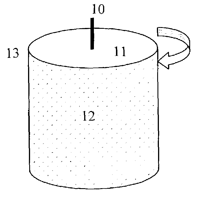
[0033]Referring to FIGS. 1a–b, we show illustrations of a side-view and top-view of a preferable embodiment of a cylinder (13) containing water(11), with preferably small holes on its external walls (12), which is rotated at high speeds around a preferably vertical axis (10), thus throwing out water droplets by centrifugal forces. Preferably, the cylinder is divided by vertical walls (depicted in this example as 14a–14h, but of course any convenient number of walls & cells can be used) into a number of cells, in order to better rotate the water and reduce internal circulations of the water (11), which would be a waste of energy. The cells can be for example wider at the circumference, as shown in FIG. 1b, or for example narrower as they reach the edges of the cylinder, as shown in FIG. 1c. Preferably, at the center of the cylinder there is an area of water free of inter...


PUM

PropertyMeasurementUnit
speedaaaaaaaaaa
droplet sizeaaaaaaaaaa
sonic speedsaaaaaaaaaa

Abstract

Many areas in the world already suffer shortages of water, and others will suffer from it in the coming years. Therefore more efficient water sweetening is essential for our survival on this planet. The most commonly used water sweetening methods are: Reversed osmosis, distillation, electrodyalisis, and partial freezing. However, these methods suffer from low efficiency and high energy consumption, thus making them significantly more expensive than naturally obtained water. The present invention describes a system & method for efficient and low energy sweetening of water, based on borderline fast fluctuation between liquid to gaseous state and back, by using centrifugal forces to make water droplets fly at a high speed, so that they evaporate for a split second, the salt is separated, and they condense again. The present invention tries to make the process energy-efficient by enabling the use of lower speeds and smaller droplet sizes and solving various problems involved with that.

Description

[0001]This patent application is a continuation-in part of PCT application PCT / IL 02 / 00806 which was filed in Israel on Oct. 3, 2002, hereby incorporated by reference in its entirety, which claims priority from Israeli patent application 145740 of Oct. 3, 2001 and from U.S. provisional patent application 60 / 344,653 of Dec. 28, 2001.[0002]This patent application claims benefit and priority from PCT application PCT / IL 02 / 00806 of Oct 3, 2002.[0003]This patent application also claims benefit and priorities from the following U.S. Provisional patent applications, hereby incorporated by reference in their entirety:[0004]60 / 344,653 of Dec. 28, 2001.[0005]60 / 417,675 of Oct. 7, 2002.[0006]60 / 422,183 of Oct. 25, 2002BACKGROUND OF THE INVENTION[0007]1. Field of the Invention[0008]The present invention relates to desalination of water, and more specifically to a system & method for efficient and low energy desalination of water, based on borderline fast fluctuation between liquid to gaseous st...

Claims


Application Information

Patent Timeline
Patent Type & Authority Patents(United States)
IPC IPC(8): C02F1/04B01D3/08B04B1/00B04B1/04C02F1/38C02F1/48B01D3/06B01D61/16C02F1/44
CPCB01D3/06B01D3/08B01D61/16C02F1/385B01D61/147C02F1/444B01D61/145B01D61/025B01D2311/04C02F1/441C02F1/48C02F2103/08B01D2311/2676Y02A20/131Y02A20/124
Inventor MAYER, YARONDECHOVICH, BORISGADASSI, HAIM
Owner BARHON MAYER BATYA
Learn More