
Hollow fiber membrane module

a technology of hollow fiber membrane and urethane resin, which is applied in the direction of moving filter element filters, filtration separation, separation processes, etc., can solve the problems of easy breakage of hollow fiber membranes, inferior economical efficiency, and urethane resin constructed as the above can hardly achieve the storage modulus of 10sup>8, and achieve the effect of practical pressure resistan

Inactive Publication Date: 2007-01-09
ASAHI KASEI KK
View PDF15 Cites 108 Cited by
  • Summary
  • Abstract
  • Description
  • Claims
  • Application Information

AI Technical Summary

Benefits of technology

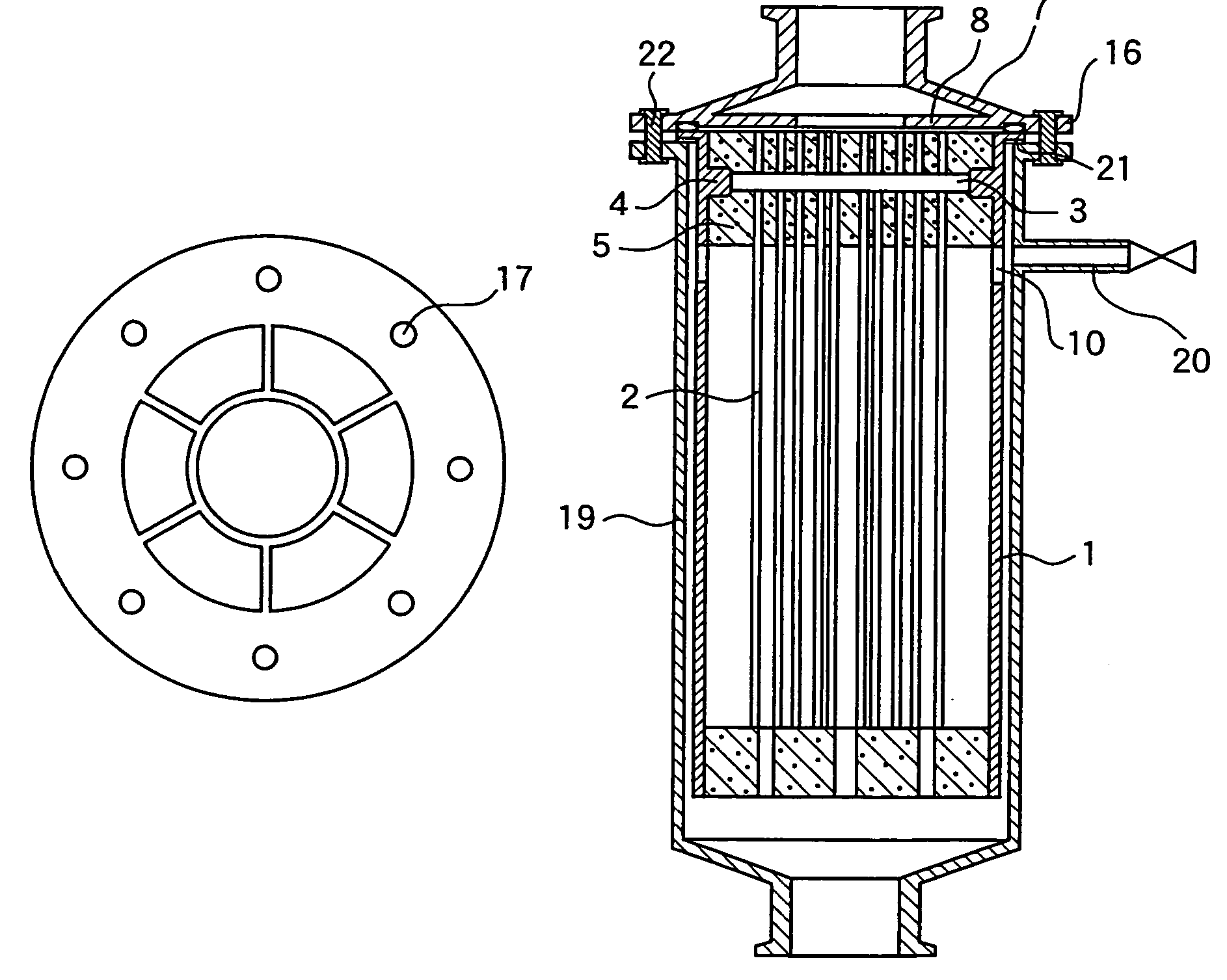
The present invention is about a hollow fiber membrane module that can withstand practical pressure. It also aims to provide a large-scale module that can resist pressure without making the potting portion thicker. Additionally, it improves the durability of the potting portion in a hollow fiber membrane module that has ozone resistance. The invention includes a hollow fiber membrane bundle fixed on a housing, a flexible potting material, and a rib or ring embedded in the potting portion without directly contacting the hollow fiber membrane. The invention also includes an external pressure filtration method using the hollow fiber membrane module.

Problems solved by technology

However, there has been a problem that high elasticity of the epoxy resin causes easy breakage of the hollow fiber membranes at the bonding interface with the epoxy resin.
However, this process has the drawback in that the bonding step had to be conducted twice, resulting in inferior economical efficiency.
However, the urethane resin constructed as the above can hardly achieve storage modulus of 108 N / m2 or more.
As a result, there are problems, in that potting portion considerably transforms by different pressure and leakage easily occurs when it is adopted for a hollow fiber membrane module having a large diameter.
However, this module construction has the problems of a complex manufacturing process and high costs because of the material for producing the unit filtration element and the beam material and of the processes for assembling these materials.

Method used


Image

  • Hollow fiber membrane module
  • Hollow fiber membrane module
  • Hollow fiber membrane module

Examples


reference example 1

[0082]A polyurethane resin prepared by mixing C-4403 (trade name) manufactured and sold by Nippon Polyurethane Industry Co., Ltd. as a main agent of urethane resin and N-4221 (trade name) manufactured and sold by the same company as a curing agent at a mass ratio (main / curing) of 63 / 37 was fed to a flanged housing (inner diameter / outer diameter: 169 mm / 183 mm) made of ABS resin in plural times, and left at an ambient temperature of 30° C. for 4 hours to cure. Then, heat settling was conducted at 50° C. for 16 hours to prepare a potting portion having a thickness of 65 mm. Herein, JIS-A hardness after curing of the urethane resin used as the potting material was 95 at 25° C. and 90 at 40° C.

[0083]Subsequently, the above-mentioned housing filled with the urethane resin was installed through a flat packing in a cylindrical pressure container made of stainless steel and equipped with a flange having bolt holes. On the flange portion of the housing, a fixing device being molded integrall...

reference example 2

[0084]The main agent and curing agent of SU-1760 (trade name) manufactured and sold by Sanyu Rec Co., Ltd. were mixed at a mass ratio (main / curing) of 20 / 80 and then fed in plural times to a flanged housing (inner diameter / outer diameter: 169 mm / 183 mm) made of ABS resin and having a ring (inner diameter: 160 mm, thickness: 15 mm, R-processing: 2 mmR) molded integrally with the housing, as shown in FIG. 23. After leaving at an ambient temperature of 40° C. for 4 hours to cure, heat settling was further conducted at 60° C. for 20 hours to prepare a potting portion 65 mm thick comprising a urethane resin as a potting material. Herein, JIS-A hardness after curing of the urethane resin was 78 at 25° C. and 71 at 60° C.

[0085]Subsequently, the above-mentioned housing filled with the urethane resin was installed through a flat packing in a cylindrical pressure container made of stainless steel and equipped with a flange having bolt holes. On the flange portion of the housing, a fixing devi...

reference example 3

[0086]A potting portion 60 mm thick comprising a silicone rubber as a potting material was prepared by mixing agents A and B of TSE-3337 (trade name) manufactured and sold by GE Toshiba Silicones Co., Ltd. at a mass ratio (agent A / agent B) of 1 / 1, feeding the mixture to a flanged housing (inner diameter / outer diameter: 157 mm / 165 mm) made of SUS-304 and having a ring (inner diameter: 137 mm, thickness: 20 mm, R-processing: 3 mmR), as shown in FIG. 23, fixed on the inner wall of the housing by welding, leaving the housing at an ambient temperature of 60° C. for 5 hours to cure, and further conducting heat settling at 120° C. for 3 hours. Herein, JIS-A hardness after curing of the silicone rubber was 60 at both 25° C. and 60° C.

[0087]Subsequently, the above-mentioned housing filled with the silicone rubber was installed through a flat packing in a cylindrical pressure container made of stainless steel and equipped with a flange having bolt holes. On the flange portion of the housing, ...


PUM

PropertyMeasurementUnit
thicknessaaaaaaaaaa
thicknessaaaaaaaaaa
thicknessaaaaaaaaaa

Abstract

A hollow fiber membrane module comprising a module housing, a hollow fiber membrane bundle comprising a plurality of hollow fiber membranes, at least one end portion of the bundle being fixed on the housing through a flexible potting material, and a rib or ring embedded in the potting portion, the rib or ring being fixed on an inner wall of the housing, and the rib or ring being embedded in the potting portion without directly contacting the hollow fiber membrane, and the filtration method using the same. The hollow fiber membrane module can maintain a practical pressure resistance.

Description

[0001]This application is the national phase under 35 U.S.C. 371 of PCT International Application No. PCT / JP02 / 11352 which has an International filing date of Oct. 31, 2002, which designated the United States of America.TECHNICAL FIELD[0002]The present invention relates to a hollow fiber membrane module used in the field of water treatment for tap water such as river water, lakes and marshes water, underground water, and underflow water; secondary treatment waste water; sea water; water for industrial use; process water; or the like. More specifically, the present invention relates to a hollow fiber membrane module in which a potting material for bonding and fixing hollow fiber membranes in a fluid tight manner to a module housing comprises a flexible material.BACKGROUND ART[0003]A hollow fiber membrane module has been widely used, for instance, for membrane filtration treatments in the production process of various industrial products such as in the production of ultrapure water fo...

Claims


Application Information

Patent Timeline
Patent Type & Authority Patents(United States)
IPC IPC(8): B01D63/02C02F1/00B01D61/00B01D63/00B01D65/02C02F1/44C02F1/78
CPCB01D63/02B01D63/021B01D63/022B01D63/023B01D65/02B01D63/024C02F1/78B01D2321/04B01D2321/168C02F1/444B01D63/0233B01D63/031B01D69/08B01D2313/041B01D2325/04
Inventor TANIGUCHI, TOHRUISHIBASHI, YUZURU
Owner ASAHI KASEI KK
Learn More