
Tapping screw

a tapping screw and screw head technology, applied in the direction of screws, threaded fasteners, fastening means, etc., can solve the problem that the female thread portion in the peripheral surface of the prepared hole is not easily broken, and achieve the effect of reducing the radial component, reducing the screwing torque, and easy screwing the tapping screw into the subj

Active Publication Date: 2007-01-09
AOYAMA SEISAKUSHO CO LTD
View PDF15 Cites 22 Cited by
  • Summary
  • Abstract
  • Description
  • Claims
  • Application Information

AI Technical Summary

Benefits of technology

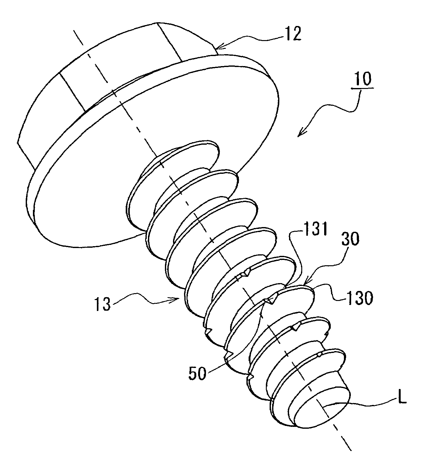
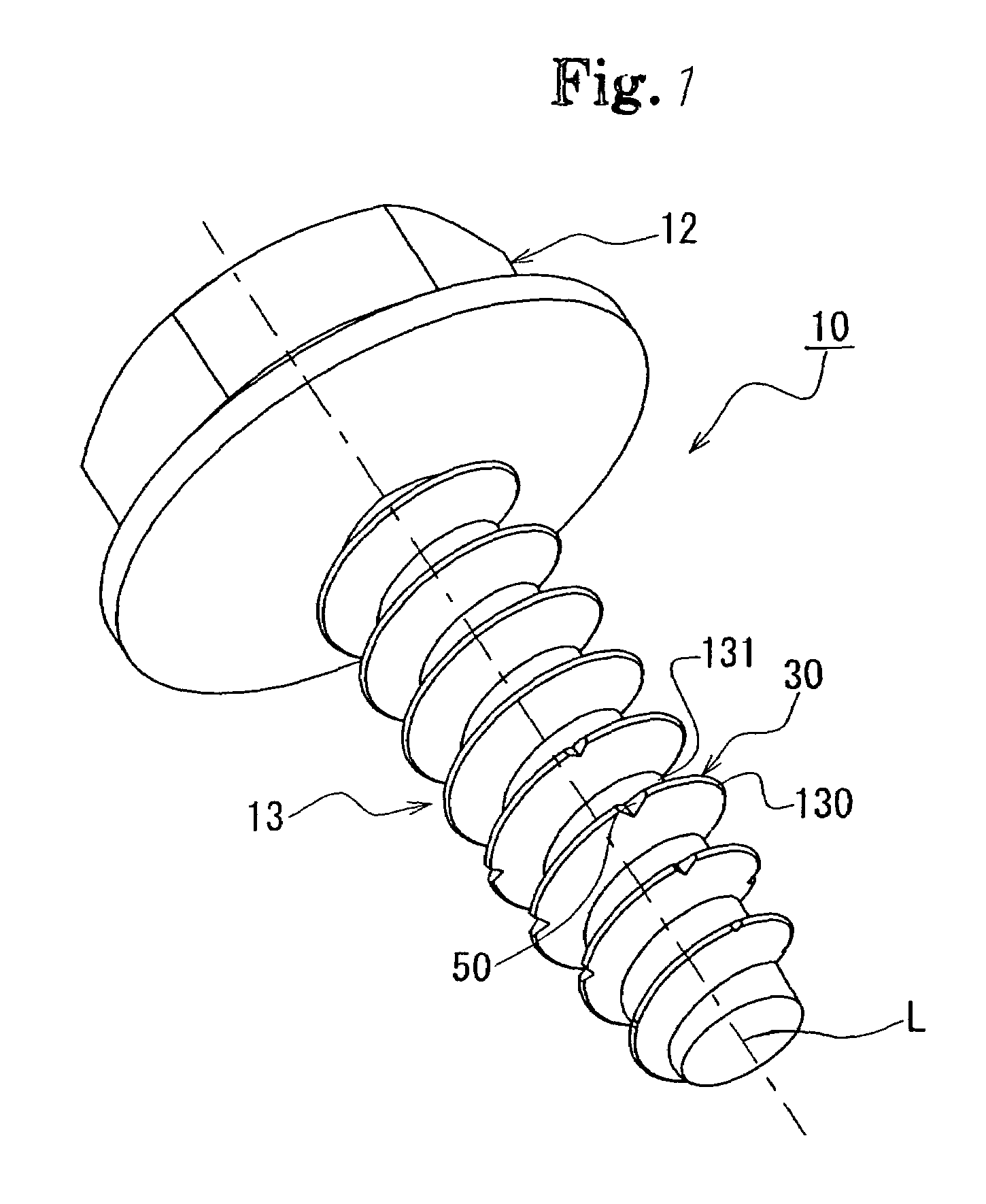
[0008]In the tapping screw in accordance with the present invention, since the angle of the thread ridge formed in the shaft portion is set to approximately 30 degrees, it is possible to make a contact area between the thread ridge and the subject small so as to lower the screwing torque, whereby it is possible to easily screw the tapping screw into the subject. Since it is possible to reduce a radial component of a force applied to the female thread portion in the peripheral surface of the prepared hole from the thread portion, that is, a force for expanding the subject in a radial direction, in accordance with making the angle of thread ridge small, it is possible to prevent the subject from being cracked. Further, since the joint portion for connecting the top portion and the bottom portion of the thread portion in the cross section including the shaft center of the tapping screw is formed in the circular arc shape in the area having the smaller diameter than the diameter of the prepared hole of the subject, it is possible to smoothly flow the excess thickness of the subject into the bottom portion of the screw at a time of screwing the tapping screw into the prepared hole of the subject, whereby it is possible to securely fasten both the members, and it is possible to increase the torque by which the female thread portion in the peripheral surface of the prepared hole is broken. Therefore, the female thread portion in the peripheral surface of the prepared hole is not easily broken. For example, in the case of fastening the tapping screw into the subject in a position in which the tapping screw is hard to be visually observed, it is possible to check out the seating of the screw on the subject only by a hand feeling, and it is possible to securely carry out a fastening work.

Problems solved by technology

Therefore, the female thread portion in the peripheral surface of the prepared hole is not easily broken.

Method used


Image

  • Tapping screw
  • Tapping screw
  • Tapping screw

Examples


Embodiment Construction

[0013]A description will be given below of a tapping screw according to the present invention with reference to the accompanying drawings. The tapping screw in accordance with the present embodiment is fastened to a resin subject, an illustration of which is omitted, while forming a female screw in a prepared hole of the subject, and can be preferably employed in the case of mounting a resin member to a vehicle body of a motor vehicle or the like.

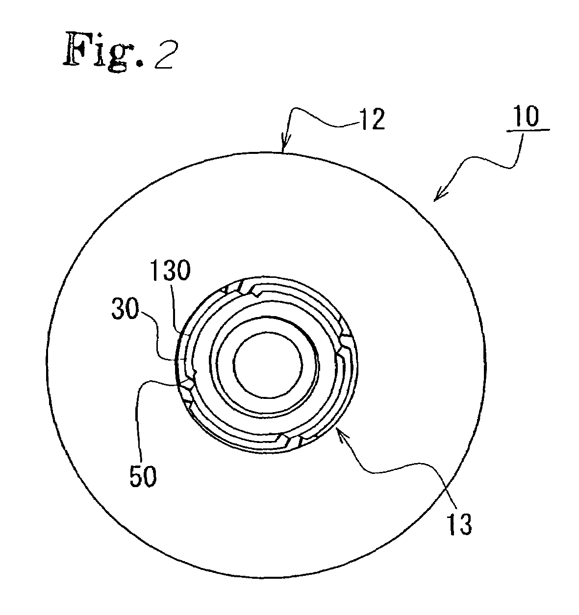
[0014]A description will be first given of an entire structure of a tapping screw 10 in accordance with the present invention with reference to FIGS. 1 and 2. As shown in FIG. 1, the tapping screw 10 is constituted by a head portion 12 and a shaft portion 13 which extend along a common shaft center L. The shaft portion 13 is constituted by a uniform diameter portion and a reduced diameter portion which is slightly pinched at a predetermined taper angle toward a leading end. A thread portion 30 is formed all along an approximately entire len...


PUM


Abstract

A tapping screw fastened to a subject member in which a thread portion formed in a shaft portion of the tapping screw is used to form a female screw thread in a prepared hole of the subject member. An angle of a thread ridge is approximately 30 degrees, a plurality of notches are formed in a top portion of the thread portion over a predetermined range of an entire length of the shaft portion, and a joint portion for connecting the top portion and a bottom portion of the thread portion is formed to have a circular arc shape in an area having a smaller diameter than a diameter of the prepared hole of the subject matter, as viewed in a cross section including a shaft center of the tapping screw.

Description

[0001]This application claims the benefit of Japanese Application No. 2003-350450, filed Oct. 9, 2003, the entirety of which is incorporated herein by reference.FIELD OF THE INVENTION[0002]The present invention relates to a tapping screw, and more particularly to a tapping screw which is fastened to a resin subject member using a threaded portion on the shaft of the screw to form a female thread in a hole formed in the subject member.BACKGROUND OF THE INVENTION[0003]There has been proposed a tapping screw which is fastened to a prepared hole in a subject member while cutting a female thread in the subject by screwing the threads on the tapping screw into the prepared hole in the subject. In the case of screwing the tapping screw into the subject particularly made of resin, there is a demand of making a screwing torque as small as possible, and making a torque (a strip torque) by which a female thread portion in a peripheral surface of the prepared hole of the subject is broken as la...

Claims


Application Information

Patent Timeline
Patent Type & Authority Patents(United States)
IPC IPC(8): F16B25/10F16B25/06F16B25/00F16B33/02
CPCF16B25/0031F16B25/0052F16B25/0047
Inventor MIZUNO, HIROMICHIKOZAWA, MITSURUYAMADA, KENYA
Owner AOYAMA SEISAKUSHO CO LTD
Learn More