Navigation system for a vehicle

Inactive Publication Date: 2007-01-02
DONNELLY CORP
View PDF31 Cites 165 Cited by
  • Summary
  • Abstract
  • Description
  • Claims
  • Application Information

AI Technical Summary

Benefits of technology

[0005]One aspect of the present invention offers a complete GPS system, including antenna, receiver and a GPS information display into a vehicular mirror assembly, and particularly an interior rearview mirror assembly. Provision of such a mirror-mounted GPS system as a unitary, complete assembly has several advantages, including obviating an automaker from having to specifically design a dashboard or other interior cabin spaces and would decrease the time to market associated with such level of feature integration. Also, provision of a mirror-mounted GPS system as a unitary, complete assembly facilitates supply of such assemblies as retrofits and as aftermarket installations, and generally increases an automaker's ability to offer a GPS feature as an option on selected vehicles.
[0007]Another aspect of this invention is the location of the GPS antenna and the receiver in the exterior side view assembly. A further aspect is the processing by that exterior side view mirror receiver of GPS location data received by the antenna and fed from there to the receiver, providing an output from that location, that is external to the vehicle cabin, into the vehicle cabin. This has the advantage of the optimal field of view for the antenna for communication to GPS satellites. The placement of the receiver in an exterior side view mirror assembly in close proximity to the antenna also is preferred to avoid RFI and EMC issues associated with low level RF signals. Locating the GPS antenna at a distance from the GPS receiver may render the GPS system subject to stray RF noise from cellular phones and high power portable transmitters, such as CB's and handheld radios.

Problems solved by technology

Map displays are currently one of the largest cost factors in vehicle navigational systems.

Method used


Image

  • Navigation system for a vehicle
  • Navigation system for a vehicle
  • Navigation system for a vehicle

Examples


Embodiment Construction

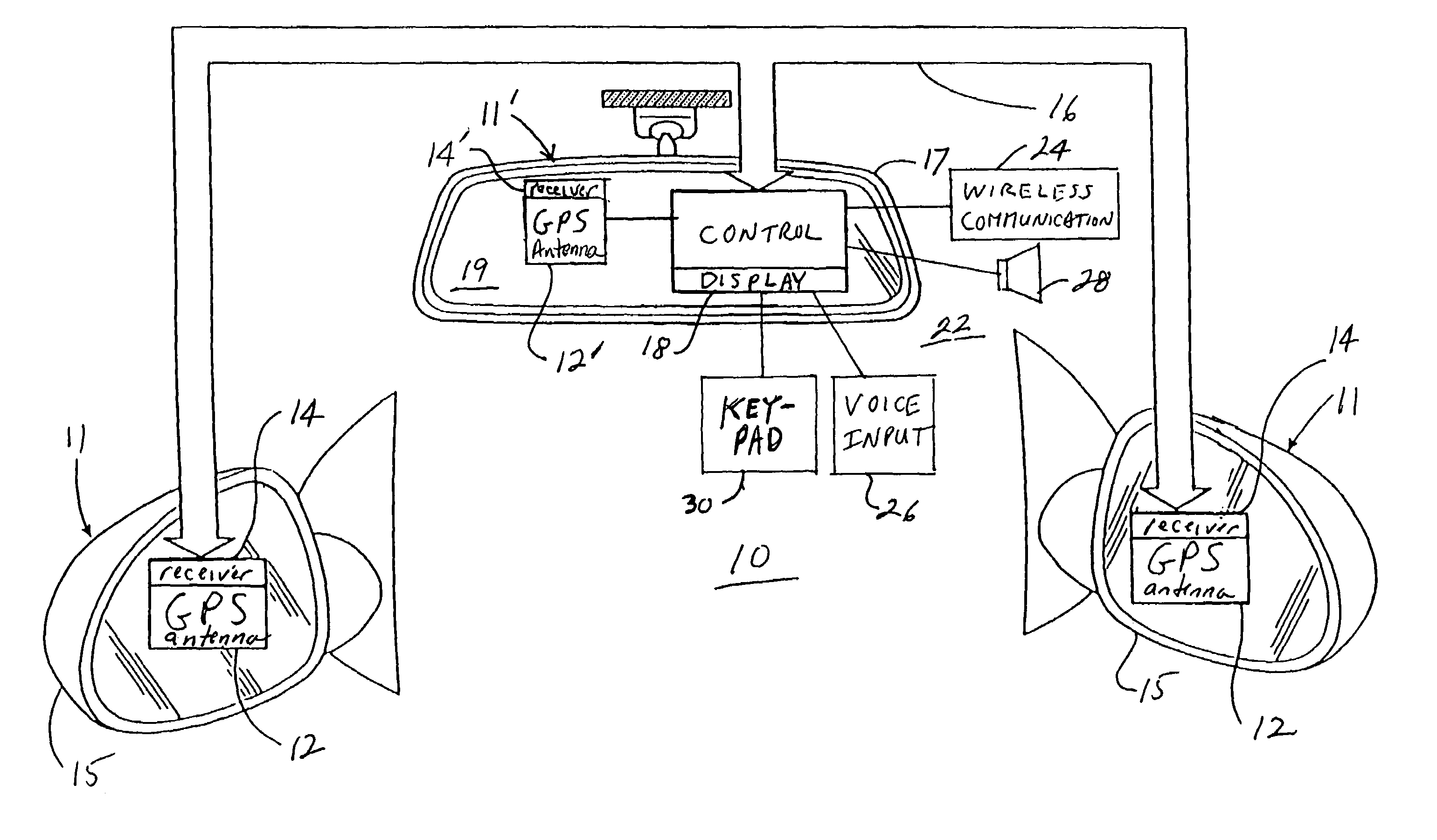
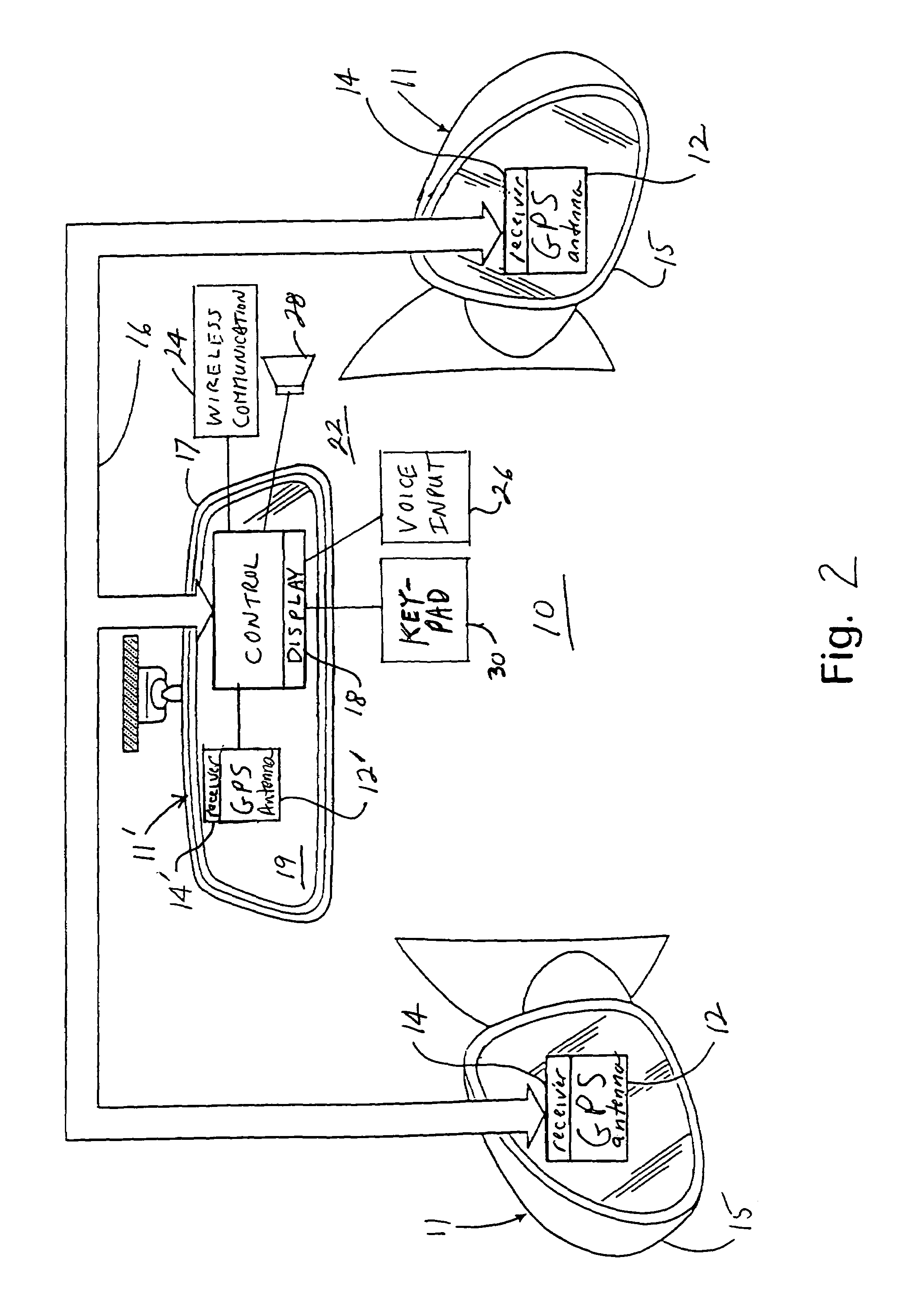
[0010]Referring now to the drawings and the illustrated embodiments depicted therein, a vehicular rearview mirror-based navigation system 10, in a preferred embodiment of the present invention, includes one or more GPS receiving systems 11 exterior mirror-mounted antennas 12 that receive location information form GPS satellites. A GPS receiver 14, to which is connected the GPS antenna 12, may also be mounted within an exterior side view mirror assembly 15. The geographic data output from the GPS receiver 14 is then transferred to an interior rearview mirror assembly 17 for display with the driver via a communication channel 16 such as by a wire connection, a vehicle data bus connection such as a LIN (Local Interconnect Network) or a CAN bus, as known in the art, or wirelessly such as via short-range RF data transmission using a protocol such as the BLUETOOTH protocol such as is available from Motorola of Schaumberg, Ill. Alternatively, a GPS receiving system 11 including an interior...


PUM


Abstract

A navigation system suitable for use in a vehicle includes an interior rearview mirror assembly having an interior reflective element. A database at a site remote from the vehicle includes map data and / or directory data. A global-positioning system receiver is operable to receive signals from satellites external to said vehicles. A transceiver is operable to engage in a wireless communication with a remote transceiver located at a site remote from the vehicle to received data derived from the database. A user input allows a user to input a destination. The system responds to an input of a destination by wirelessly communicating the destination to the remote transceiver and downloading directions. A display that displays turn-by-turn instructions to the destination during the road journey based on the downloaded directions and on the signals received by the global-positioning system receiver. The turn-by-turn instructions may include (i) direction, (ii) when to turn, and / or (iii) how far until the turn. The navigation system preferably includes a short-range wireless communication link.

Description

CROSS-REFERENCE TO RELATED APPLICATION[0001]This application is a continuation of patent application Ser. No. 10 / 287,178, filed on Nov. 4, 2002, now U.S. Pat. No. 6,678,614, which is a continuation of patent application Ser. No. 09 / 799,414, filed on Mar. 5, 2001, now U.S. Pat. No. 6,447,464, which claims priority from U.S. provisional patent application Ser. No. 60 / 187,960, filed on Mar. 9, 2000, the disclosures of which are hereby incorporated herein by reference in their entireties, and is a continuation-in-part of U.S. patent application Ser. No. 09 / 449,121, filed on Nov. 24, 1999, now U.S. Pat. No. 6,428,172 B1.BACKGROUND OF THE INVENTION[0002]Vehicle-based global-positioning systems (GPS) are capable of providing complete mapping information, including street layout, street names, directions, landmarks, addresses, and the like. However, consumers often have difficulty reading maps, especially when presented on a video screen, and the study of complex information, such as a map ...

Claims


Application Information

Patent Timeline
IPC IPC(8): G01C21/26B60R1/12G01S19/48B60R11/00B60R11/02G01C21/36G01S5/14G01S19/35G06Q20/00
CPCB60R1/12B60R11/0247G09B29/10G01C21/3626G01S19/35G01S19/36G01S19/37G01C21/36B60R11/0241B60R2001/1284B60R2011/0026B60R2011/0033G01S19/21B60R1/04B60R2300/8026G01C21/34G01S19/13
Inventor MCCARTHY, KEVIN CUHLMANN, EUGENIE VLYNAM, NIALL R
Owner DONNELLY CORP
Why Eureka
Try Eureka