
Waffle stud for insert molded plastic members

a technology of insert molded plastics and studs, which is applied in the direction of threaded fasteners, screwdrivers, manufacturing tools, etc., can solve the problems of low spin-out torque value of conventional fasteners, localized stress created in plastic materials, and requiring substantially thicker plastic components to encapsulate, etc., to achieve low cost of manufacture, simple and effective use, and durable construction

Active Publication Date: 2007-01-02
FORD GLOBAL TECH LLC
View PDF46 Cites 24 Cited by
  • Summary
  • Abstract
  • Description
  • Claims
  • Application Information

AI Technical Summary

Benefits of technology

The fastener achieves high spin-out torque and pull-out force values with reduced localized stress in plastic materials, ensuring strong attachment and durability in molded components.

Problems solved by technology

Conventional fasteners suffer from the problem of having high profiles on the head portion, thus requiring substantially thicker plastic components to encapsulate the head portion.
Conventional fasteners also suffer from having low spin-out torque values, e.g. the amount of torque applied to the threaded shaft of the fastener that will cause the head portion to break away from the plastic encapsulation.
Another problem associated with the insert molding of fasteners into plastic components is the localized stress created in the plastic material by the shape of the head portion of the fastener.
Square-headed fasteners, for example, have a significant amount of localized stress at the corners of the head portion where the plastic material has to flow around the sharp corner of the head portion.
Thus, a carriage head fastener would generate much lower localized stresses in the plastic material, but have a highly undesirable spin-out torque value for most plastic part applications in the automotive industry.

Method used


Image

  • Waffle stud for insert molded plastic members
  • Waffle stud for insert molded plastic members
  • Waffle stud for insert molded plastic members

Examples


Embodiment Construction

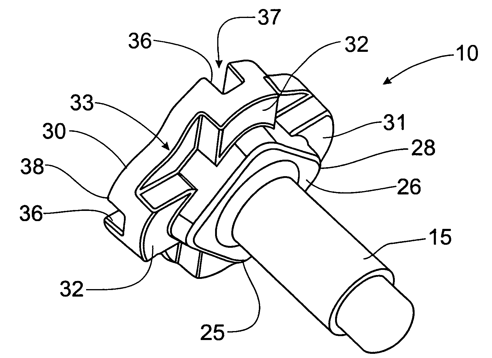
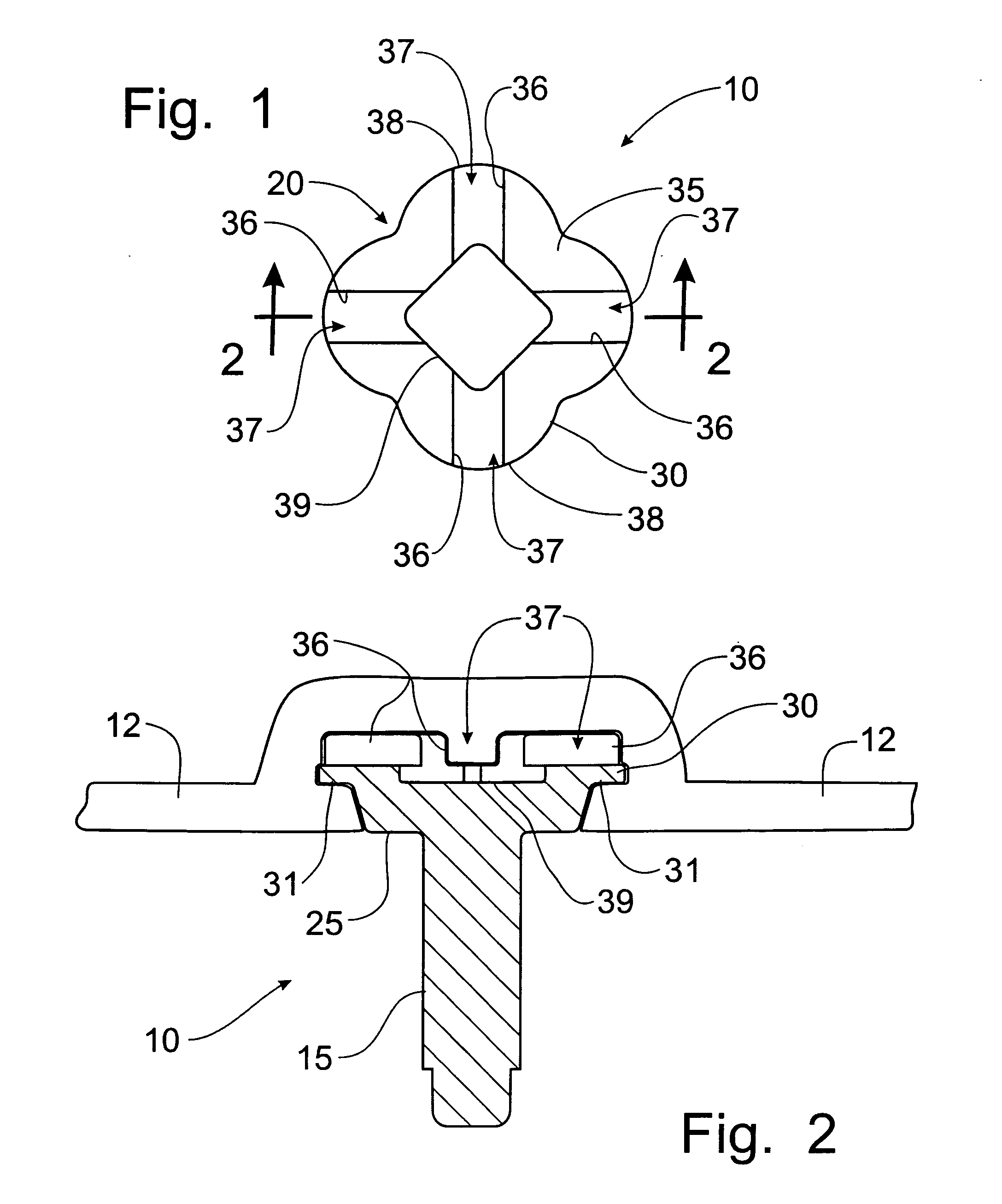
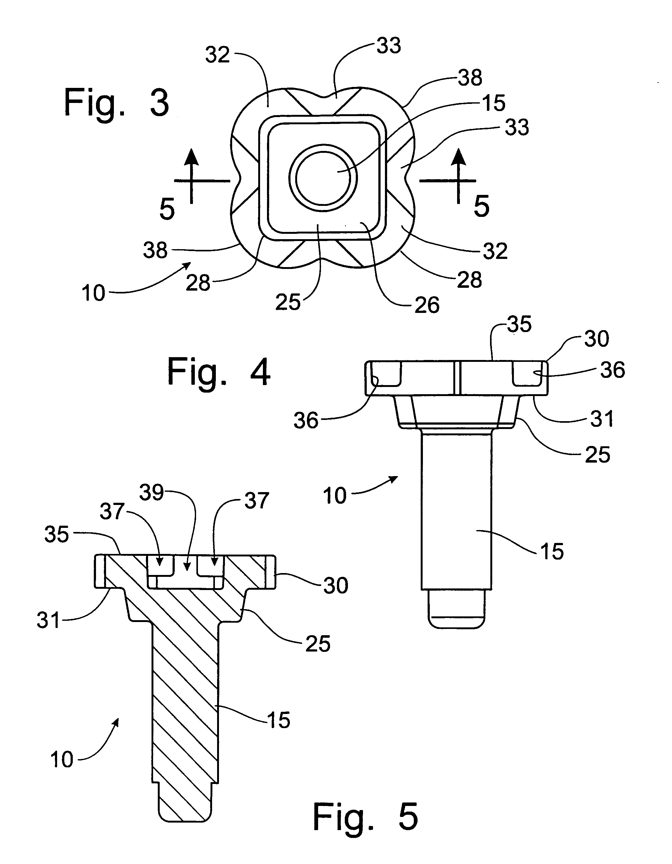
[0037]Referring to the drawings, FIGS. 1–7, a fastener incorporating the principles of the instant invention can be seen. The fastener 10 is designed for use in insert molding processes where the fastener 10 is placed into a mold having a shape corresponding to the plastic component to be formed thereby such that the shank portion 15 of the fastener 10 projects outwardly from the plastic material being inserted into the mold, with the head portion 20 encapsulated in the plastic material. The shank portion 15 can be threaded or be formed as a push-pin as is typical in use in the automotive industry.

[0038]The head portion 20 has a lower part 25 and an upper part 30. Each of the upper and lower parts 25, 30 is preferably about three millimeters in height (measured in relation to the axis of the shank 15) to provide a low profile head portion 20 that will encapsulate in conventionally molded plastic components. Blow-molded plastic components are formed typically with a thickness of thre...


PUM


Abstract

A fastener is configured for use in the manufacture of molded plastic components that will be subsequently attached to other components by the fastener. The low profile head portion of the fastener has a rounded contoured and convoluted top surface to facilitate the flow of plastic material around the head portion during the molding process. The underside of the head portion is formed with a square face surrounded circumferentially by circumferential land surfaces that provides a high pull-out force resistance for the fastener. The square face on the underside and convoluted top surface of the head portion provides a high spin-out torque resistance without sacrificing the pull-out force resistance. The rounded edges of the head portion are compatible with molding processes to allow the flow of plastic material to fully encapsulate the head portion within the molded plastic component.

Description

CROSS-REFERENCE TO RELATED APPLICATIONS[0001]This application claims domestic priority on U.S. Provisional Patent Application Ser. No. 60 / 580,697, filed Jun. 18, 2004, the contents of which are incorporated herein by reference.BACKGROUND OF THE INVENTION[0002]Molded plastic parts are utilized in many manufacturing processes. In machinery manufacturing processes, such as the manufacture of automotive vehicles, the plastic parts are attached to other components of the vehicle to create the final assembled product. The attachment of the molded plastic parts to other components typically requires the utilization of fasteners attached to the molded plastic part to permit a selective detachable connection to the component on which the plastic part is to be mounted.[0003]Molding of the plastic part can be accomplished in one of several known processes, including injection molding and blow molding, which can provide finished plastic parts. It is known in the art of molding plastic component...

Claims


Application Information

Patent Timeline
Patent Type & Authority Patents(United States)
IPC IPC(8): F16B39/282F16B39/02F16B23/00F16B19/00F16B19/02F16B35/06F16B37/04
CPCF16B19/02F16B37/048F16B35/06Y10T16/476
Inventor TIBBENHAM, PATRICIADEAN, DAVIDZAYDEL, WIESLAWWINOWSKI-ZAYDEL, MICHELLE
Owner FORD GLOBAL TECH LLC
Learn More