
Method for enhancing cyclonic vessel efficiency with polymeric additives

Inactive Publication Date: 2006-12-26
BAIR PATRICK W +1
View PDF12 Cites 30 Cited by
  • Summary
  • Abstract
  • Description
  • Claims
  • Application Information

AI Technical Summary

Benefits of technology

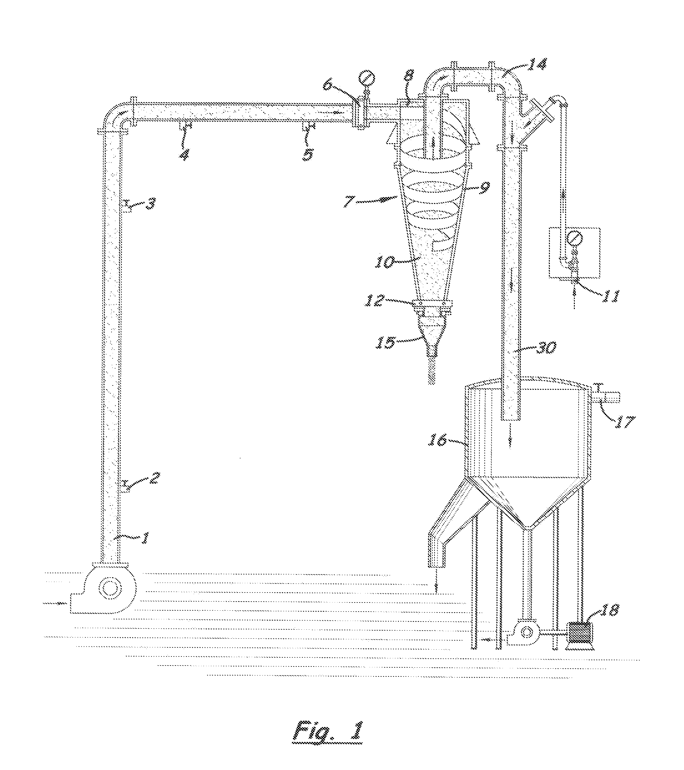
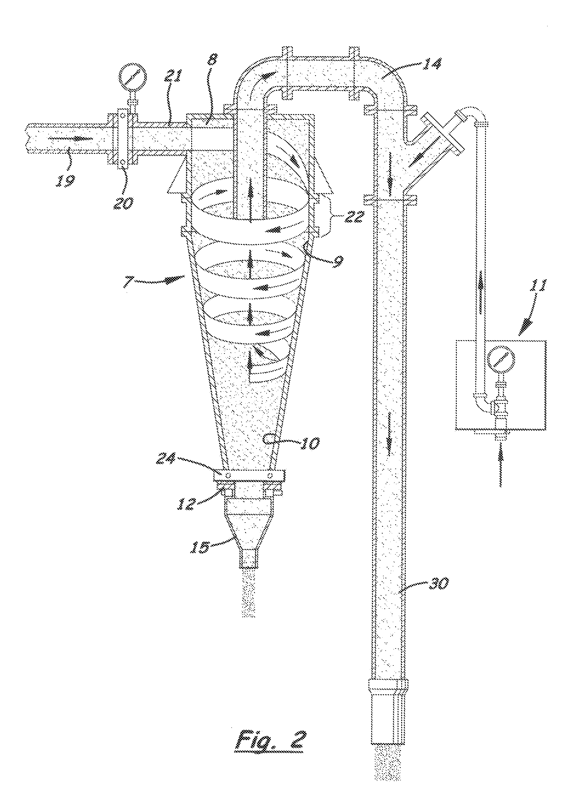
[0034]According to the first aspect of the invention, a novel method for combining specific polymeric additives in a liquid stream containing fine suspended solid particles to enhance cyclone performance. The object of the invention being to increase fine particle size and strength to withstand angular (rotational), axial, and radial, and other forces, thereby dramatically increasing solids underflow discharge volume, along with lower suspended solids in the overflow. The method preferably includes the following steps:
[0047](d). An optional additional upper cone section for added mixing of polymer additives with fine solid particles. This enlarged chamber will also act to reduce particle carry-over by reducing turbulence caused by tangential, axial, rotational, or other forces.

Problems solved by technology

The efficient and cost effective removal, and or recovery of very fine solids has presented many problems for various mineral and aggregate producers over the years.
The primary disadvantage to these devices being the inability to remove very fine size solid particles without resorting to multiple small diameter units.
Even then, these cyclonic vessels are typically unable to remove solids smaller than −325 mesh.
Numerous attempts to add polymeric additive(s) prior to the cyclone have been disappointing.
This is largely due to the extremely high vector forces inside the hydraulic centrifugal vessel shearing the flocculated particles.
This operation is quite costly, and disruptive to normal plant activities, additionally, manpower and machinery normally dedicated to production must be employed for this task.
Additional disadvantages to this system include the loss of water from the ponds due to evaporation,.
Disadvantages for this system are many, including the large amount of land needed to accommodate the solids.
Energy consumption for the many pumps to move the slurry through the dike system.
Water consumption, especially in times of drought.
Additionally, new environmental permitting processes are becoming more stringent and costly to meet.
The cost and space requirements for the Settlers is large, and requires several operators to oversee.
Upsets in the Settlers can lead to large amounts of fines to be filtered.
This significantly slows the process, thus increasing production costs.
Fine solids escaping the filtration step can cause undesirable impurities such as iron or titanium in the final product.
All of the aforementioned methods and devices suffer from several deficiencies:
None of the prior art incorporate polymeric additives to increase the size of fine particles introduced into the hydrocyclone unit.
Space requirements are often large, and all require some type of supervision and maintenance.
Additionally, these processes do not eliminate the need for a clarifier, thickening tank, or holding pond, since the fine solids cannot be removed within one piece of equipment.
The combinations of equipment required are quite costly.
Equipment wear and tear is high, due to the abrasive nature of the fine solids.
Some applications, such as titanium dioxide pigment productions, and aluminum “red mudfiltration cannot be economically performed using current cyclone technology, due to excessive fine particle carry-over.
Such reductions in suspended fine solids can lead to lower equipment and space requirements, a decrease in energy requirements, along with recapture of valuable products.

Method used


Image

  • Method for enhancing cyclonic vessel efficiency with polymeric additives
  • Method for enhancing cyclonic vessel efficiency with polymeric additives
  • Method for enhancing cyclonic vessel efficiency with polymeric additives

Examples


examples 1 to 5

[0105]To provide statistical data to substantiate the unique functions of the polymeric additives on fine size particle removal from a fluid stream, a standardized test procedure was employed. This procedure being as described below.

[0106]A representative 5 gallon sample of the fine size particle stream was obtained for testing. The concentration of total suspended solids, as expressed in percent (%) was first determined. Next, 400 ml samples of various polymeric additive solutions were prepared by inverting with a hand-held mixer, such as that supplied by Braun Inc. To 400 mls of plant (on-site) clean water in a 1000 ml beaker, 1 ml of neat polymer, or polymer blend, was injected and stirred with the mixer at high speed for 20 seconds. This produced a 0.25% solution, by volume, for subsequent testing.

[0107]Testing entailed agitating the 5 gallon sample to evenly distribute the particles, then extracting a 500 ml aliquot in a 1000 ml beaker. 5–10 ppm (1–2 mls) of the cationic coagul...

example 1

[0109]

TABLE 1Granite fines slurry from quarry wash water and sand screwoverflow. Fines concentration @ 83,000TSS (8.3% solids)with 91.5% of fines passing through 200 mesh screen.Polymer TreatmentppmTSSObservations 1).Cationic Coag10 ppm83,000No Effect-Total Shear 2).Cationic Coag 5 ppmAnionic A / N10 ppm—No Effect-Total Shear 3).Cationic Coag 5 ppmAnionic N10 ppm72,300Small Effect-Highly Sheared 4).Cationic Coag 5 ppmAnionic L10 ppm—No Effect-Total Shear 5).Cationic Coag 5 ppmAnionic M10 ppm—No Effect-Total Shear 6).Cationic Coag 5 ppmAnionic H10 ppm—No Effect-Total Shear 7).Cationic Coag 5 ppmAnionic N10 ppmCationic MAP10 ppm67,400Small Flocs-Shears with mixing 8).Cationic Coag 5 ppmAnionic N10 ppmCationic L10 ppm69,500Small Flocs-Shears with mixing 9).Cationic Coag 5 ppmAnionic N10 ppmCationic M10 ppm62,200Med Flocs-Shears with mixing10).Cationic Coag 5 ppmAnionic N10 ppmCationic H10 ppm42,900Med / Large Flocs-Medium shear11).Cationic Coag 5 ppmAnionic N10 ppmCationic B-M10 ppm 8,450L...

example 2

[0111]

TABLE 2Sandstone fines slurry from quarry wash waterand sand screw overflow. Fines concentrationis 7350TSS (0.735% solids), with 100% offines passing through 200 mesh screen.92% passing through 325 mesh screen.Polymer TreatmentppmTSSObservations1).No treatment—7350No Treat2).Cationic Coag 5 ppm—No increase in size3).Anionic N 5 ppm6130small increase in size4).Anionic M 5 ppm—No increase5).Anionic H 5 ppm—No increase6).Anionic N 5 ppmCationic B-H 5 ppm1140Large flocs-undertreat7).Anionic N 5 ppmCationic B-H10 ppm 48Large / strong-clear water8).Anionic N 5 ppmCationic H 5 ppm3120Large flocs-start to break9).Anionic N 5 ppmCationic H10 ppm 883Large flocs-slight breakup

[0112]Table 2 shows a similar effect to that in Table 1, but without the need for the cationic coagulant. Again, the effectiveness of the structured cationic copolymer to resist shear is clearly demonstrated, providing greater than 99.5% removal of fine size particles from the fluid medium.


PUM

PropertyMeasurementUnit
Fractionaaaaaaaaaa
Fractionaaaaaaaaaa
Fractionaaaaaaaaaa

Abstract

The present invention is directed to a novel method and system for enhancing the efficiency of hydraulic centrifugal separators (cyclones) in the removal of fine size particles from a liquid carrying medium. More particularly, it is concerned with improvements in the removal efficiency of any number of cyclonic devices that rely on the use of centrifugal force to separate fine size particles of differing density from the liquid carrying medium by addition of polymeric additives, both before, and, as necessary, inside the cyclone body.

Description

BACKGROUND OF THE INVENTION[0001]1). Field of the Invention[0002]The present invention relates to a method for removing, and / or recovering fine size particles from a liquid carrying medium utilizing devices which separate under the influence of centrifugal force disposed within a vortex body, through the addition of polymeric additives The present invention also relates to a system for recovering fine size particles from the liquid carrying medium utilizing devices which separate under the influence of centrifugal force disposed within a vortex body. The method and system have particular applicability in the mineral aggregates industry, including, but not limited to; phosphate production, granite, sandstone, limestone, and igneous rock production. Additionally, alumina manufacture via the Bayer Process, and Titanium Dioxide manufacture via the Chloride Process, as well as waste neutralization tailings from the same Chloride / Sulfate process, may also utilize this method and system.[0...

Claims


Application Information

Patent Timeline
IPC IPC(8): C02F1/56B01D21/00C02F1/00C02F1/38
CPCB01D21/0018B01D21/0042B01D21/01B01D21/2444B01D21/2461B01D21/26C02F1/56C02F1/38C02F2001/007C02F2301/024C02F2301/026
Inventor BAIR, PATRICK WBAIR, CHARLYNN
Owner BAIR PATRICK W
Learn More