
Surface treated doctor blade

a blade and surface treatment technology, applied in the field of doctor blades, can solve the problems of preventing partial wear during running-in time, affecting the scraping property and property of ink scraping blades, and affecting the production efficiency of printing presses

Inactive Publication Date: 2006-12-26
NIHON NEW CHROME
View PDF20 Cites 18 Cited by
  • Summary
  • Abstract
  • Description
  • Claims
  • Application Information

AI Technical Summary

Benefits of technology

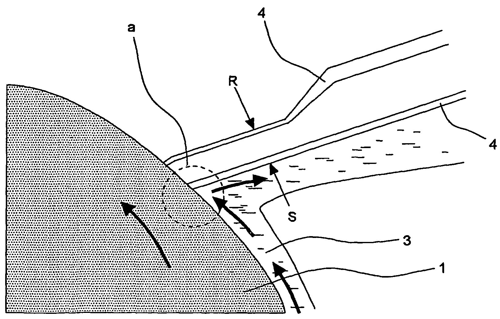
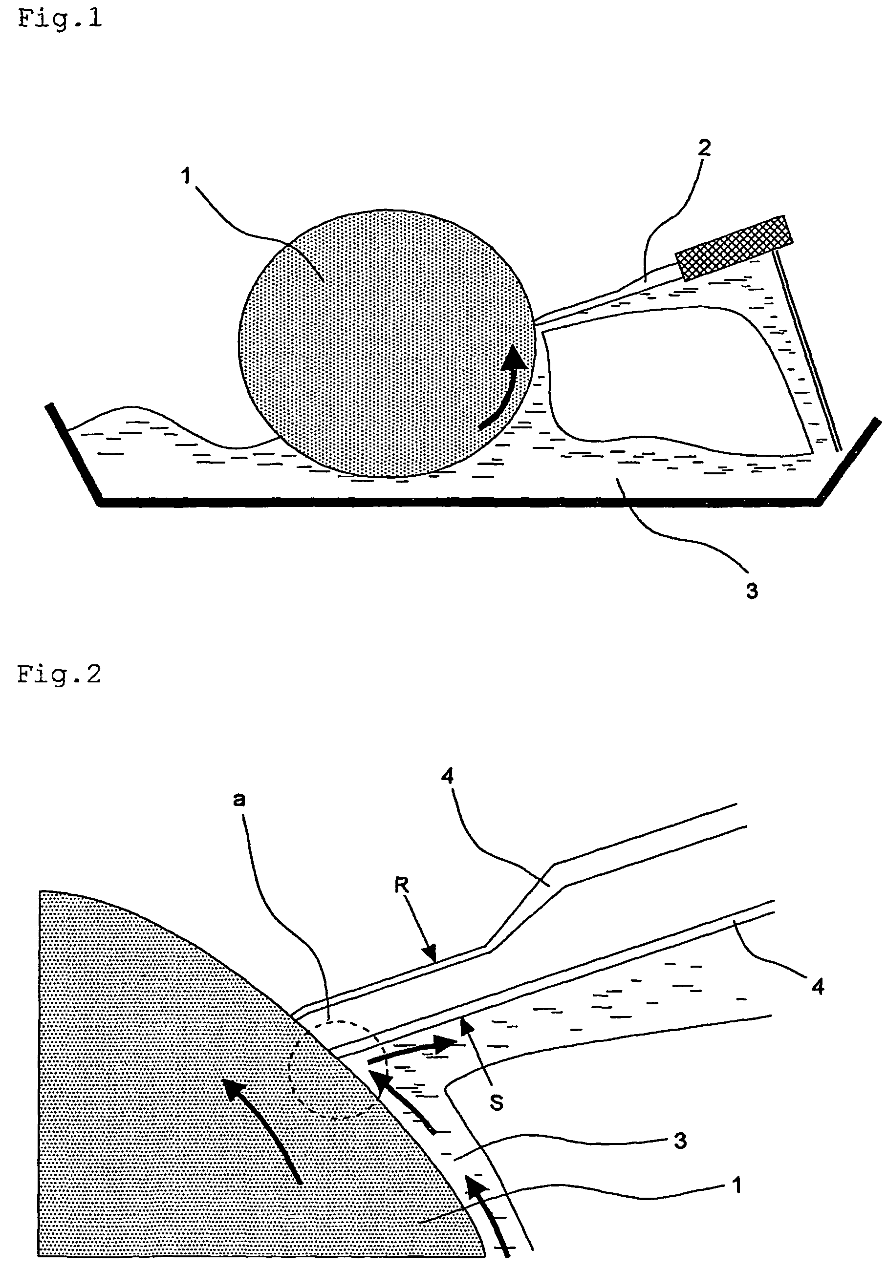
[0022](1) To reduce the surface energy of the outermost treated blade surface at least on the front side (the front side with respect to the direction to which the cylinder rotates) of the blade edge end in contact with the ink. It is to be assumed that by reducing the surface energy, the surplus ink scraped off the non-image portion does not stay due to the ink repellency of the coating film, and is efficiently discharged from the system through the contact area between cylinder and blade (portion a in FIG. 2), with the result that engulfing of ink into the inner portion (failure in scraping off of ink by the blade) is restrained.
[0023](2) To set the surface hardness of the blade after treatment within a specific range. It is to be assumed that by setting plating hardness within a specific range, it is possible for the blade to apply a stable, uniform, and sufficient pressure onto the cylinder, thereby improving the ink scraping performance.
[0025](3) To reduce coefficient of friction of the blade surface, that is, to enhance lubricity of the surface and restrain cohesion wear at the point of contact between the blade and the cylinder;
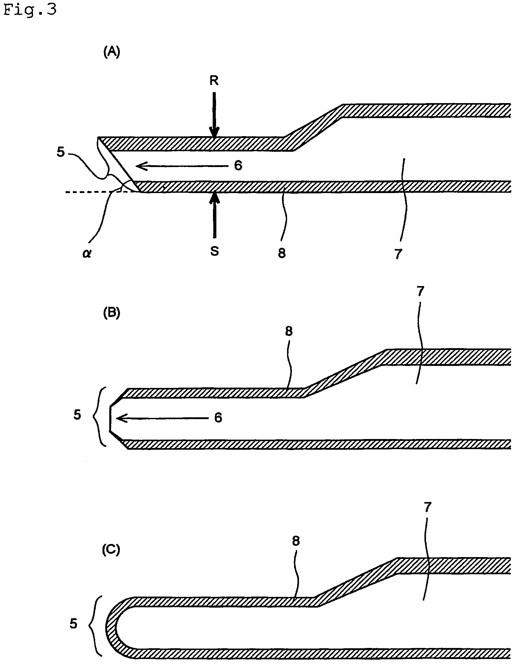
[0030](6) To improve conformability of the blade edge end, it is effective to reduce hardness of the blade edge end portion (5 in FIG. 3), which is the first part of the blade to come into contact with the cylinder. It is not definitely known why this improves the conformability of the blade edge end. However, it is to be assumed that by reducing the hardness, deformation of the blade edge end when being pressed on the cylinder is encouraged, and as a result, the area of the blade portion coming into contact with the cylinder increases, which contributes to improvement in conformability of the blade edge end. Specifically, it is most effective to expose the blade base material exclusively at the blade edge end.
[0031](7) Further, in order to prevent partial wear during running-in time which is caused by exposure of the blade base material for increasing the area coming into contact with the cylinder, it is necessary to provide a coating film having lubricity on surface treated portion of the blade edge other than the portion where the base material is exposed.
[0032]It has been confirmed that, in order to improve conformability of the blade edge end, in addition to improvement of the ink scraping property and property for continuous printing (wear resistance), it is effective to form the surface treatment coating film in a double-layered structure to allot different functions to each coating film layer and to expose only the blade edge end portion of the blade base material.

Problems solved by technology

It is to be assumed that printing failures in the form of bleeding, blurring, fogging, etc. of the image generated between the early stage and the middle stage of continuous printing are mainly attributable to a failure in scraping ink off by the blade.
It is to be assumed that by reducing the surface energy, the surplus ink scraped off the non-image portion does not stay due to the ink repellency of the coating film, and is efficiently discharged from the system through the contact area between cylinder and blade (portion a in FIG. 2), with the result that engulfing of ink into the inner portion (failure in scraping off of ink by the blade) is restrained.

Method used


Image

  • Surface treated doctor blade
  • Surface treated doctor blade
  • Surface treated doctor blade

Examples


example 1

Plating Process 1;

[0116]A single-and-parallel-edged steel base material for doctor blade (steel strip having a total length of 50 m) having a plate width of 50 mm, a plate thickness of 0.15 mm, a blade edge width of 1.4 mm, and a blade edge end thickness of 0.07 mm was spirally taken up on a reel together with a spacer consisting of a metal steel strip which had the surface roughened by embossing treatment, and in the state in which it was wound around the reel, it was immersed for 15 minutes in an alkali degreasing solution (Pakuna RT-T (manufactured by Yuken Industry Co., Ltd.), 60 g / L) of 50° C. After being washed in water, it was subjected to a hydrochloric acid activation treatment in a hydrochloric acid activation liquid for 15 minutes, and was then further washed in water. Thereafter, it was immersed in an electroless Ni plating solution in which SiC particles having an average particle size of 0.5 μm were dispersed (plating solution manufactured by Japan Kanigen Co., Ltd.; S...

example 2

Plating Process;

[0136]A single-and-parallel-edged steel base material for doctor blade (steel strip having a total length of 50 m) having a plate width of 50 mm, a plate thickness of 0.15 mm, a blade edge width of 1.4 mm, and a blade edge end thickness of 0.07 mm was spirally taken up on a reel together with a spacer consisting of a rough wire mesh, and in the state in which it was wound around the reel, it was immersed for 15 minutes in an alkali degreasing solution (Pakuna RT-T (manufactured by Yuken Industry Co., Ltd.), 60 g / l) of 50° C. After being washed in water, it was subjected to a hydrochloric acid activation treatment in a hydrochloric acid activation liquid for 15 minutes, and was then further washed in water. Thereafter, it was immersed in an electroless Ni plating solution in which SiC of an average particle size of 0.5 μm were dispersed (plating solution manufactured by Japan Kanigen Co., Ltd.; Sumer SC-80-1: 20 vol %, Sumer SC-80-4; 2 vol %) at 87° C. until a predete...

example 34

Plating Process 1;

[0146]A single-and-parallel-edged steel base material for doctor blade (a steel strip having a total length of 50 m) having a plate width of 50 mm, a plate thickness of 0.15 mm, a blade edge width of 1.4 mm, and a blade edge end thickness of 0.07 mm was continuously subjected to electrolysis (Pakuna Erekuta J (manufactured by Yuken Industry Co., Ltd.): 50 m / l, NaOH: 50 g / l, 30° C., 2.5 A) and washed in water. Thereafter, electric chromium plating (chromic anhydride: 250 g / l, H2SO4: 2.5 g / L, HEEF25C: 20 ml / l, bath temperature: 50° C.) was performed on the specimen, adjusting the plating current and plating time so as to attain a predetermined plating thickness, to thereby prepare a single-layer chromium-plated blade 1.

Surface Adjustment Process;

[0147]Buff polishing was performed on the above-mentioned single-layer chromium-plated blade 1 to completely remove the plating residues or the like from the surface, thereby obtaining a single-layer chromium-plated blade 2.

P...


PUM


Abstract

Disclosed is a surface treated doctor blade in which the surface of at least the blade edge portion thereof consists of a surface treatment coating film composed of a first layer consisting of a specific nickel-based plating and a second layer provided thereon which has low surface energy, and in which preferably at least a part of the blade edge end portion of the blade base material is exposed. In the surface treated doctor blade of the present invention, it is possible to improve wear resistance of the blade edge end and to suppress generation of printing failures during continuous printing. Further, in the mode in which at least a part of the blade base material is exposed, it is possible to reduce running-in time for adjustment of contact of the blade edge with the cylinder after replacement of the doctor blade.

Description

RELATED APPLICATION[0001]This application is a 35 USC 371 national stage application of international application PCT / JP03 / 00777 filed Jan. 28, 2003.TECHNICAL FIELD[0002]The present invention relates to a doctor blade having on its surface a double-layered coating film. More specifically, the present invention relates to a surface treated doctor blade which is superior in suppressing a printing failure attributable to the doctor blade that is caused during continuous printing.BACKGROUND ART[0003]As shown in FIG. 1 and FIG. 2 (which is a partial enlarged view of FIG. 1; it is to be noted that in both FIGS. 1 and 2, the blade portion is, for ease of understanding, depicted extremely large as compared with the cylinder), in gravure (intaglio) printing, a cylinder (1) having on its peripheral surface a large number of minute recesses (not shown) called cells corresponding to an image is used. A doctor blade (2) formed of steel or stainless steel is pressed against the peripheral surface...

Claims


Application Information

Patent Timeline
Patent Type & Authority Patents(United States)
IPC IPC(8): D21G3/00B41F9/10
CPCB41F9/1072B41N10/005Y10T428/12937Y10T428/12014Y10T428/12028Y10T428/12056
Inventor URATA, KAZUYAONIWA, NAOYUKITACHIBANA, KUNIO
Owner NIHON NEW CHROME
Learn More