
Eccentric coupling device in radial compliance scroll compressor

a scroll compressor and eccentric coupling technology, which is applied in the direction of machines/engines, rotary/oscillating piston pump components, liquid fuel engines, etc., can solve the problems of degrading the performance of the scroll compressor, increasing the gas pressure in the compression chamber, and affecting the operation of the scroll compressor. , to achieve the effect of simple structure and convenient fitting of the stopper

Inactive Publication Date: 2006-12-19
LG ELECTRONICS INC
View PDF22 Cites 19 Cited by
  • Summary
  • Abstract
  • Description
  • Claims
  • Application Information

AI Technical Summary

Benefits of technology

The present invention provides an eccentric coupling device in a radial compliance scroll compressor that prevents a pressure difference between upper and lower ends of an eccentric bush due to dispersion of oil, prevents the eccentric bush from rising axially when it repeats forward and backward movements during the compression operation of the scroll compressor, and prevents an eccentric bush carrying a stopper from rising axially at either a normal position or a rotated position. The device includes a crank pin, a bush with a crank pin hole, a stopper fitted in the stopper hole, and a vertical movement preventing device at the upper end of the crank pin. The vertical movement preventing device may include an engagement jaw or an engagement disc. The device achieves these technical effects with a simple structure and is easily replaceable.

Problems solved by technology

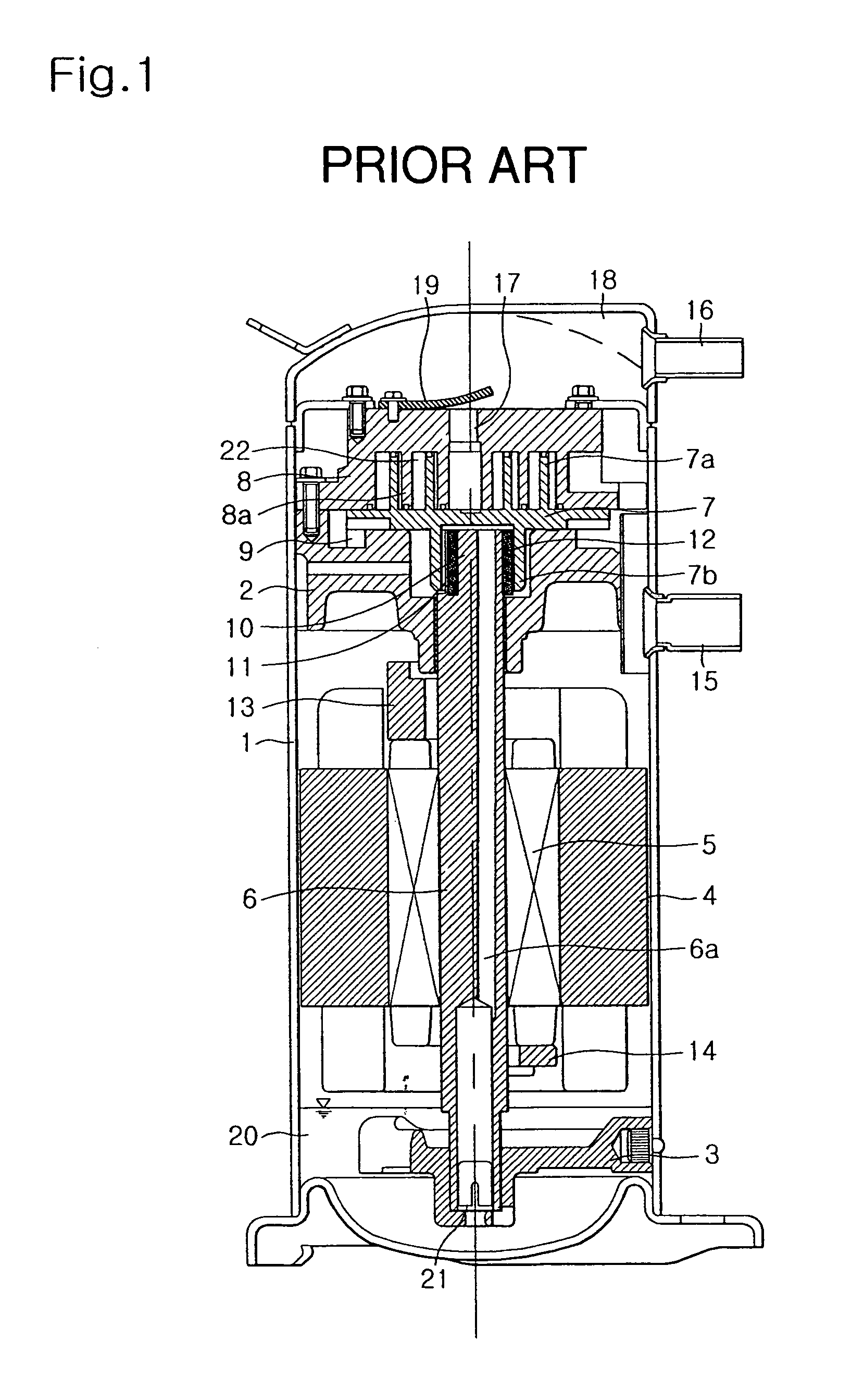
In such a radial compliance scroll compressor, an orbiting scroll thereof is backwardly moved when liquid refrigerant, oil or foreign matter is introduced into compression chambers defined between the orbiting scroll and the other scroll, that is, a fixed scroll, thereby abnormally increasing the gas pressure in the compression chambers.
As a result, the mechanism of the scroll compressor may be damaged.
Furthermore, the performance of the scroll compressor may be degraded.

Method used


Image

  • Eccentric coupling device in radial compliance scroll compressor
  • Eccentric coupling device in radial compliance scroll compressor
  • Eccentric coupling device in radial compliance scroll compressor

Examples


Embodiment Construction

[0052]Now, embodiments of an eccentric coupling device in a radial compliance scroll compressor according to the present invention will be described with reference to the annexed drawings.

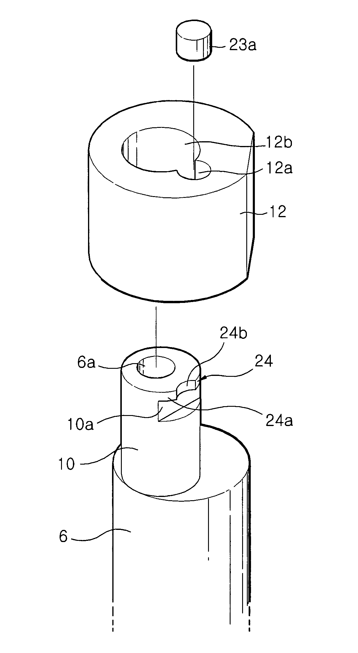
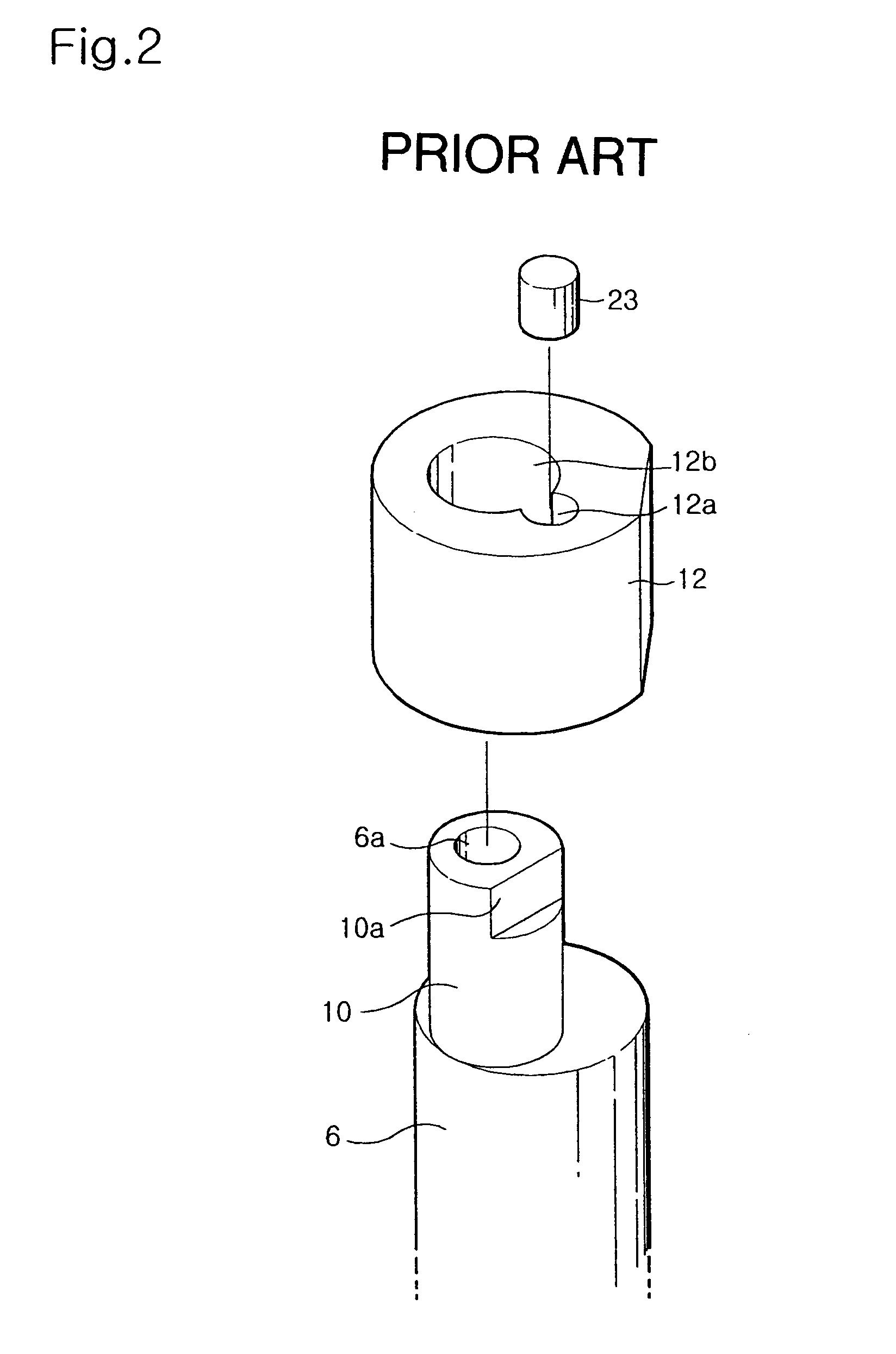
[0053]FIG. 4 is an exploded perspective view illustrating an eccentric coupling device according to an embodiment of the present invention. The eccentric coupling device may be applied to the radial compliance scroll compressor shown in FIG. 1. In order to simplify the description thereof, the eccentric coupling device will be described in conjunction with the case in which it is applied to the radial compliance scroll compressor shown in FIG. 1. In FIG. 4, elements respectively corresponding to those in FIGS. 1 and 2 will be designated by the same reference numerals.

[0054]As shown in FIG. 4, the eccentric coupling device includes a crank pin 10 provided at an upper end of a crankshaft 6 such that it is eccentrically arranged with respect to the crankshaft 6, an eccentric bush 12 rotatably fitted a...


PUM


Abstract

An eccentric coupling device in a radial compliance scroll compressor including a crank pin eccentrically arranged at an upper end of a crankshaft included in the scroll compressor, and provided with a vertically-extending cut surface at one side thereof, a bush fitted around the crank pin, and provided with a crank pin hole and a stopper hole, a stopper fitted in the stopper hole, and an engagement jaw adapted to prevent a vertical movement of the stopper, thereby preventing a vertical movement of the bush, the engagement jaw being provided at an upper end of the crank pin. The bush is arranged such that an upper end thereof is flush with an upper end of the crank pin. The stopper hole overlaps with the crank pin hole so that the stopper selectively comes into contact with the cut surface in accordance with a rotation of the crank pin. The stopper has a length shorter than that of the stopper hole.

Description

BACKGROUND OF THE INVENTION[0001]1. Field of the Invention[0002]The present invention relates to a scroll compressor, and more particularly to an eccentric coupling device in a radial compliance scroll compressor, which is capable of preventing abnormal behavior of an eccentric bush caused by a pressure difference between upper and lower ends of the eccentric bush during operation of the scroll compressor, while preventing the eccentric bush from rising axially.[0003]2. Description of the Related Art[0004]Generally, a scroll compressor includes upper and lower scrolls respectively provided with involute-shaped wraps engaged with each other. One of the scrolls performs an orbiting motion with respect to the other scroll to reduce the volume of spaces defined between the scrolls, thereby compressing gas confined in the spaces.[0005]As such a conventional compressor, a radial compliance scroll compressor is known. In such a radial compliance scroll compressor, an orbiting scroll thereo...

Claims


Application Information

Patent Timeline
Patent Type & Authority Patents(United States)
IPC IPC(8): F04C18/02F03C2/00F04C18/00F04C29/00F04C29/02
CPCF04C18/0215F04C29/0057F04C29/023F04C29/028F04C2240/50F04C2270/72F04C18/02
Inventor KIEM, MYUNG-KYUNYOO, BYUNG-KILYOO, DONG-WON
Owner LG ELECTRONICS INC
Learn More